• ROS
  • OAK-D Pro Wide ROS camera_info calibration interpretation

Hi,
we're running an OAK-D Pro Wide PoE (P/N: A00574, D/C: 5023) and are unsure whether we're applying the factory calibration (published as a CameraInfo ROS message) correctly. We created a small test setup consisting of the camera looking on a 4-by-4 STag marker grid, run marker detection and reprojection, and the expected result is that the red circle's centers coincide with marker origins, however, as you can see, that is not the case, except of the right eye's image:
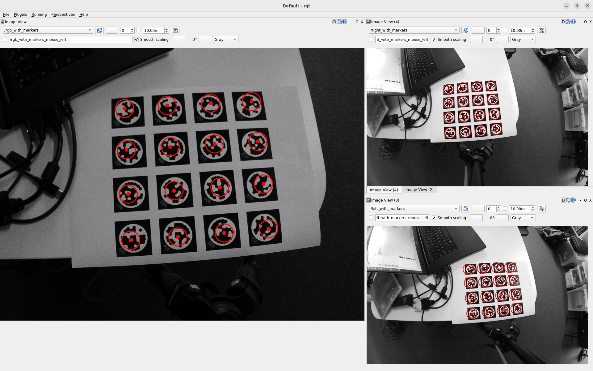
The setup is as follows:

  • A stag_ros node detects markers in the right image and publishes their poses.
  • A custom ROS node subscribes to all images and the marker poses, and projects the 3D poses onto the 2D images. It takes into account the baseline published on TF (copied manually into the script) and the R, K and D matrices.

For the right image, the marker observations align perfectly, indicating that the applied projection is exactly the inverse of what stag_ros does. (Actually, stag_ros doesn't take into account the camera's R matrix, so upon receipt of the marker poses, we rotate all points by the transpose of the right camera's R matrix.)

Here's the current projection code:

void projectMarkersToImageCoordinates(
    const std::vector<stag_ros::STagMarker> markers, 
    const sensor_msgs::CameraInfo & camera_info,
    const cv::Point3d & camera_position,
    std::vector<cv::Point2d> & uvs) {
  // Ensure output is empty
  uvs.clear();
  // Nothing to project => exit
  if (markers.empty()) return;
  // Prepare input
  std::vector<cv::Point3d> object_points;
  for (const stag_ros::STagMarker& m : markers) {
    object_points.push_back(cv::Point3d(
      m.pose.position.x - camera_position.x,
      m.pose.position.y - camera_position.y,
      m.pose.position.z - camera_position.z));
  }
  cv::Mat r(3, 3, CV_64F);
  for (int i = 0; i < 9; ++i) r.at<double>(i) = camera_info.R[i];
  cv::Mat rvec;
  cv::Rodrigues(r, rvec);
  cv::Mat tvec = cv::Mat::zeros(cv::Size(3, 1), CV_64F);
  cv::Mat k(3, 3, CV_64F);
  for (int i = 0; i < 9; ++i) k.at<double>(i) = camera_info.K[i];
  // Assume distortion model follows OpenCV format
  cv::Mat d(camera_info.D.size(), 1, CV_64F);
  for (int i = 0; i < camera_info.D.size(); ++i) d.at<double>(i) = camera_info.D[i];
  // The actual 3D => 2D projection
  cv::projectPoints(object_points, rvec, tvec, k, d, uvs);
}

I attempted to add the full source file, however, the forum responded that the file type is not supported.

The above code is classic OpenCV, and it corresponds to what the existing stag_ros node does, so I guess it's close to correct. But perhaps we're still missing something.

Could you please share your thoughts on whether we're interpreting and using the calibration correctly? If anything is unclear, please let know.

  • Calibration appears to have been fixed in a recent driver update. Thanks!

5 days later

Hi, sorry for the delay, by looking at pictures directly:

  • I assume that Stereo is aligned to right sensor which is why it looks good
  • Left image detections are shifted, which could indicate that the baseline is read incorrectly. I suspect this might be because of alignment (stereo is aligned to the right and IIRC in OpenCV it is aligned to the left). You can change that behavior in depthai_ros_driver (more information here)
  • RGB detections seem to be shifted based on distance from the center, which indicates that the distortion parameters might not be parsed correctly (or they are applied but on a rectified image)

If it would be possible for you to share some rosbags we could investigate further.

    Hi Luxonis-Adam , thank you for your reply.

    The current analysis treats the three images as independent, i.e. not as stereo. It doesn't use the P matrices at all. It does use the TF with the baseline, and the D, K and R matrices, though.

    Can I send you a private message or email with a link to the bag file and all code?

    @Luxonis-Adam you can find the bag file and the code here. It should be sufficient to reproduce it, either using the bag file or using a Luxonis camera.

    6 days later

    Hi @Luxonis-Adam, I hope you got some time to look into the rosbag and the code shared last week. Could you already share some insights?

    6 days later

    Hey, sorry for the delay, I have looked through the information and I am not very familiar with stag_ros package but I'm not sure if that setup will work as intended.

    1. As I see, marker positions are detected on distorted image
    2. They are not rectified(?) after that
    3. Due to them not being rectified their positions are distorted as in right camera plane
    4. Other sensors have separate distortion parameters (and resolution in case of rgb, that's why circles appear smaller)
    5. I would try undistorting those points and project them on rectified images, that should provide more accurate positions

    Hi,

    1. As I see, marker positions are detected on distorted image

    Correct.

    1. They are not rectified(?) after that

    The rectification (CameraInfo.R) is applied on the received marker positions in the method markersCallback in the reproject_markers.cpp (this file is in the zip shared on Google Drive), as the stag_ros node does not take into account CameraInfo.R. The inverse of the right camera's R is applied, as R describes the rotation from the reference frame (RGB cam here) to the right camera's frame, while here we want to transform the other way. The stag_ros node takes into account distortion (CameraInfo.D) when solvePnp is called, which takes distortionMat (= the distortion coefficients) as argument. I think it should work out like that?

    Both distortion and rectification are taken into account when projecting the marker points back from 3D to 2D in projectMarkersToMimageCoordinates (shared in the first post), in cv::projectPoints. Those 2D points match those of what stag_ros detected, so stag_ros must be applying the same distortion correction (in the other direction, then). Though I may be missing something?

    That said, in the end the stag_ros package just provides some 3D positions. If the camera calibration is correct and the projection as well (the function projectMarkersToImageCoordinates), then each 3D position should be projected to the 'same' location in each image, with 'same' meaning here that it coincides with the same real-life features. The stag_ros node is just used to let it coincide with the markers, with eases visual interpretation.

    10 months later

    Calibration appears to have been fixed in a recent driver update. Thanks!