Hello everyone,

I'm working with an OAK-D SR PoE camera and trying to control the GPIO pin available on the M8 AUX connector (specifically, Pin 7).
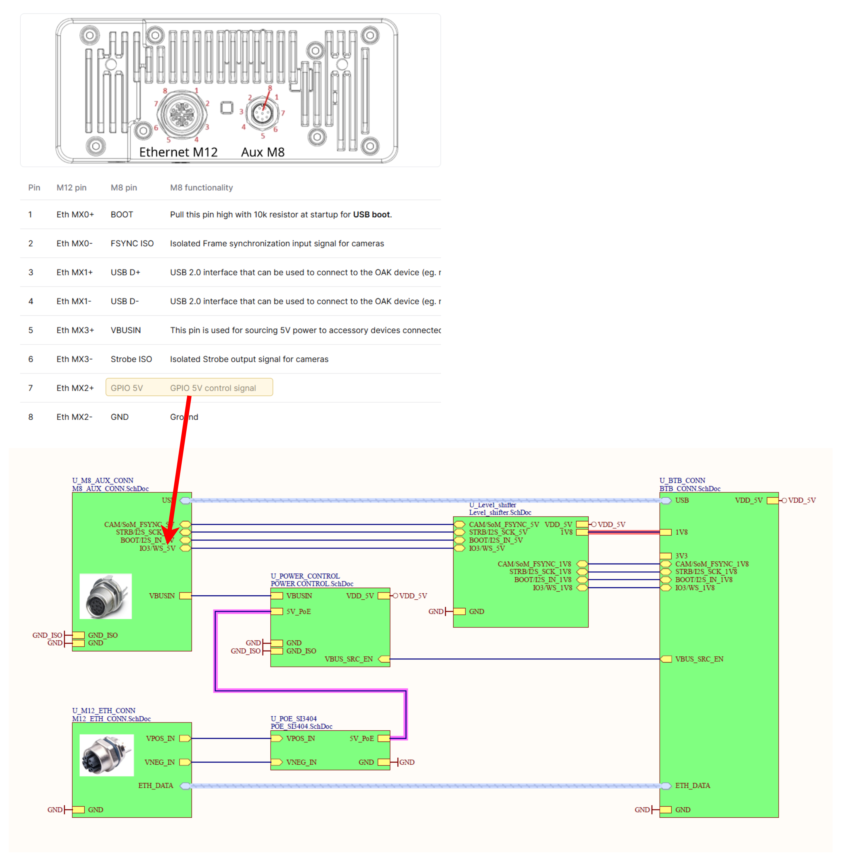
In my opinion this pin should be controllable with GPIO-Pin-Number 30. Here's the test script I created:

'''

This Script purpose is to Test the functionality of the GPIO Pin of OAK-D SR PoE

GPIO Pin is located at AUX M8-connector: Pin 7

'''

#!/usr/bin/env python3

import depthai as dai

import time

# Create pipeline

pipeline = dai.Pipeline()

gpioScript = pipeline.create(dai.node.Script)

# setting Properties of Script Node

gpioScript.setProcessor(dai.ProcessorType.LEON_CSS)

script_gpio_test = (f"""

import GPIO

import time


GPIO_TEST_PIN = 30

GPIO.setup(GPIO_TEST_PIN, GPIO.OUT, GPIO.PULL_DOWN)

toggleVal = True

while True:

node.warn('GPIO toggle: ' + str(toggleVal))

toggleVal = not toggleVal

GPIO.write(GPIO_TEST_PIN, toggleVal)  # Toggle the GPIO

time.sleep(10)   

"""

)

gpioScript.setScript(f"{script_gpio_test}")

# Connect to device and start pipeline

with dai.Device(pipeline) as device:

device.setLogLevel(dai.LogLevel.DEBUG)

device.setLogOutputLevel(dai.LogLevel.DEBUG)

print('Connected to OAK')

while not device.isClosed():

    time.sleep(1)

With this script, I expected Pin 7 on the M8 AUX connector to toggle every 10 seconds. However, the toggle is occurring on Pin 5 instead.

Questions:

  • Am I misunderstanding the GPIO mapping for this device?

  • Could there be an error in the documentation, with the "GPIO 5V control signal" actually referring to Pin 5 on the M8 AUX connector instead of Pin 7?

Any insights or similar experiences would be appreciated!

    FabianTresch In my opinion this pin should be controllable with GPIO-Pin-Number 30. Here's the test script I created:

    Try GPIO29.

    Thanks,
    Jaka

    4 days later

    Hello Jaka

    Thank you for your response—using GPIO Pin 29 worked perfectly, and the toggling now occurs as expected on Pin 7 of the M8 AUX connector.

    However, I have a question: where can I find this information in the documentation? From the schematic on GitHub, it’s not clear to me that GPIO 29 corresponds to this pin.

    I also have one more question: is there a way to control the onboard LED of the OAK-D SR PoE?

    Thanks again for your help!

      FabianTresch
      The schematics are for R0. Though I looked through the PCB and seems like the same pin is connected to MX50 not 30 so I am not sure which connection you were looking at. MX50 changed to MX29 from R0 to R2.

      I urged the ee team to update the repo.

      Thanks,
      Jaka

      You're absolutely right; my initial reference was incorrect—I actually meant the MX50. Here you can see what schematic I have in front of me:

      Do you have also an answer to the question: Is there a way to control the onboard LED of the OAK-D SR PoE?

        FabianTresch

        FabianTresch Is there a way to control the onboard LED of the OAK-D SR PoE?

        Afaik no since the LED is connected directly to BOOT pins which are only controllable through FW and generally shouldn't be changed since device needs them to know the current boot state (BOOTED/UNBOOTED/RECOVERY/etc).

        Thanks,
        Jaka