• Hardware
  • How to get precise external timing on OAK-D S2 POE

Hello everyone

I have a challenge. I'm attempting to get the OAK-D S2 POE cameras to accept external trigger and strobe signals.

Reading the documentation made me believe that it ought to be really simple. Unfortunately, from what I understand, that is not the case.

Timing is crucial since I use this camera over a conveyer belt in a number of scenarios. As a result, I intended to allow FSYNC to receive a trigger signal from the PLC, which manages the conveyor belt and other components. The scene should then be captured by the three cameras—two of which are monochrome and the other one are RGB. I want to link the strobe signal to the PLC so it can precisely determine when the scene was recorded in order to ensure flawless timing.But things are rather hard because I'm utilising RGB sensors with rolling shutters (IMX378). due to the fact that this sensor is not particularly suitable for random timing capture.

I'm considering setting all of the cameras to static at 20 frames per second. The processor will then select the first scheduled shot for the cameras and send it to the host if the PLC determines that it is time to trigger. In order to inform the PLC of the exact moment the scene was recorded, the strobe (or another external M8 compatible output) will also be toggled.

I need to know which GPIOs are connected to which and whether there are any additional bottlenecks before I can attempt to make this tweak using the scripting possibilities.

We welcome any information regarding this or any other solutions to this difficulty!

I appreciate your time and attention.

Hi @fredrik ,
I think using GPIO to read when to "capture" frames would be the best option as you mentioned, and then Script node can be used to determine which frames to send to the host.
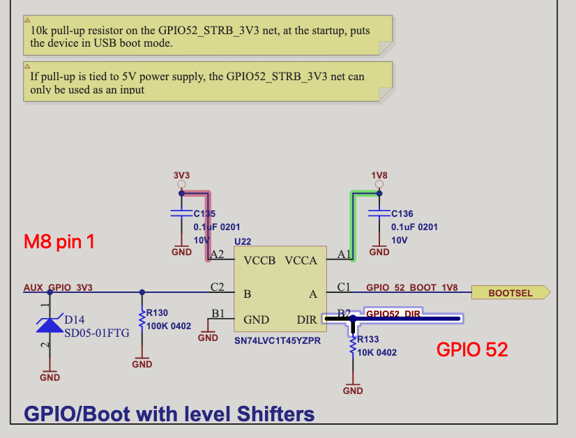
Looking at connectors, you could use pin1 on m8 connector for GPIO (which is processors pin 52):
https://docs.luxonis.com/projects/hardware/en/latest/pages/NG9097s2/#connectors
WRT Strobe, you could log when you received a gpio signal (log timestamp), as imgFrame carries information about the capture time and exposure time.
Thoughts?
Thanks, Erik

Hello, @erik.

Thank you for your prompt reply.

Using GPIO52 appears to be the most effective solution.

But this pin does not have any protection like the FSYNC, correct?
Can the FSYNC and STROBE GPIOs be used in a different way than they are currently?
Is this not achievable because of firmware or hardware issues?

I will keep you updated about the solution.

Best wishes! Fredrik

Hi @fredrik ,
There is a level shifter (3v3 <-> 1.8). FSYNC signal is connected to the Myriad X chip directly, but depthai FW uses it unless the cameras generate the FSYNC signal themselves. STROBE is not connected to Myriad X, only to the cam sensor.

    erik

    Hi @erik ,

    thanks for the explanation. The FSYNC is probably not needed to read as an IO since time logging is already supported in the firmware as far as I know.

    To which cam is the STROBE connected?

    Is there a description about the timing of the STROBE signal? In this case it's the blue signal. I didn't get yet why it's not one single pulse and what the edges mean.

    Hope to hear from you.

    Hi @Luxonis-Alex, do you perhaps know why the strobe has the strange short pulse (rising back up)?

      @fredrik STROBE signal on OAK-D-S2-POE is connected to the left stereo camera (OV9282). It pulls (or should pull) the signal low during the entire exposure of the camera.

      Hi @fredrik,
      For the scope capture above, how were the camera nodes being configured in the pipeline? And the upper signal (ch 1) is applied on FSYNC?
      For the continuous streaming with external sync mode, camera FPS should be set to match precisely the input signal rate (e.g. .setFps(20)) and this applied as well: .initialControl.setFrameSyncMode(dai.CameraControl.FrameSyncMode.INPUT)
      That weird pulse might happen if there's a mismatch between camera sensor internal timings (configured by setFps) and the external signal. Can also check how that signal looks like if the FSYNC signal is not provided - static level. A particularity of OV9282 is that if the signal is missing, the sensors continue to stream at the configured FPS. They will align to the external signal if provided, but its rate needs to stay very close to setFps rate.

        Pin 5 (VBUS) by default is an input for receiving power (it could also be an alternative to PoE, but only if the application doesn't have high power requirements, depending on what it uses - neural networks, video encoder etc), so no voltage present is expected.

        It can be configured as an output if desired by your application (could power some external circuitry), and I believe this should do it, for example from a Script node:

            VBUS_OUT_GPIO_CTRL = 9
            GPIO.setup(VBUS_OUT_GPIO_CTRL, GPIO.OUT, GPIO.PULL_NONE)
            GPIO.write(VBUS_OUT_GPIO_CTRL, 1)  # Enable 5V output

          Luxonis-Alex

          I'm sorry. I tested it again and now it seems to work correctly. I'm not sure if it was hard or software:

          Now all cameras are controlled by .setFps.

          @alex @Luxonis-Alex

          I'm able to get warned if the state on the aux GPIO changes.

          But I don't understand how to use the interrupt function within this script block. I found the Script in the Nodes section, but an example with an interrupt implemented would help a lot.

          The next step is to receive the timer that drives the cameras in the script section. Any ideas, examples or documentation on this?

          My idea is as follows:

          • The three cameras are running on the highest FPS
          • Start a counter if there is a pulse on AUX GPIO
          • Count until the scene is captured and send this time to the host

          Do you think the script area will be the place to let this happen?

          Thanks for your help!

          @Luxonis-Alex @erik

          I made this Script:
          script.setScript("""
          import time
          import GPIO


          VBUS_OUT_GPIO_CTRL = 9
          GPIO.setup(VBUS_OUT_GPIO_CTRL, GPIO.OUT, GPIO.PULL_NONE)
          GPIO.write(VBUS_OUT_GPIO_CTRL, 1)  # Enable 5V output
          
          AUX_GPIO = 52    
          GPIO.setup(AUX_GPIO, GPIO.IN, GPIO.PULL_DOWN)
          
          GPIO.setInterrupt(AUX_GPIO, GPIO.RISING, 1)
              
          ctrl = CameraControl()
          ctrl.setCaptureStill(True)
          while True:
              node.warn('waiting for interrupt')
              GPIO.waitInterruptEvent()
              node.io['out'].send(ctrl)

          """)

          When I'm putting a 10 Hz signal on the AUX GPIO the system works for around 1 minute, then I get this message:
          [1944301061CA801300] [192.168.88.253] [83.028] [system] [critical] Fatal error. Please report to developers. Log: 'Fatal error on MSS CPU: trap: 00, address: 00000000' '0'

          [1944301061CA801300] [192.168.88.253] [1708082326.696] [host] [warning] Monitor thread (device: 1944301061CA801300 [192.168.88.253]) - ping was missed, closing the device connection

          Any ideas on this?

          @fredrik Your code looks good. I can reproduce the same type of failure, with the 10Hz 3.3V signal applied on pin 1 (AUX_GPIO_3V3). I just replaced the script content from this example luxonis/depthai-pythonblob/main/examples/Script/script_camera_control.py
          with yours from above. Sometimes it runs for a few minutes, but eventually fails the same. Will debug this firmware problem.

          An unrelated note is that AUX_GPIO_3V3 also has another GPIO to control the direction (of a 3.3V<->1.8V level shifter), but by default the 3.3V side is an input, so this code is optional:

              AUX_GPIO_DIR_CTRL = 6   
              GPIO.setup(AUX_GPIO_DIR_CTRL, GPIO.OUT, GPIO.PULL_NONE)
              GPIO.write(AUX_GPIO_DIR_CTRL, 0)  # AUX_GPIO_3V3 (52) direction control: 0=input, 1=output

          Mentioning just in case at some point is desired to set it as output. (We should also see about abstracting these in FW.)

          However about the usage of .setCaptureStill, internally this doesn't trigger a new frame capture, but just sets a flag for the new frame from the camera to be processed/sent on the ColorCamera .still output. So by default the camera would stream at the 30fps rate, unsynced. I'm not exactly sure if this suits your needs, or you would rather want to change the cameras to fsync-input mode, for example editing in:
          luxonis/depthai-pythonblob/main/utilities/cam_test.py
          to uncomment cam[c].initialControl.setFrameSyncMode(dai.CameraControl.FrameSyncMode.INPUT)
          and applying an e.g 12V 10Hz signal on FSYNC (M8 pin 2, with GND_ISO on pin 7), then run:
          python3 utilities/cam_test.py -rs -cams rgb,c left,m right,m -fps 10

          It's still possible to add a script to get events on FSYNC GPIO (which goes both to sensors and to an SoC pin), but currently it might suffer from the same issue that it might crash the app after some time:

          script = pipeline.create(dai.node.Script)
          script.setScript("""
              import GPIO
              import time
          
              # Note: level gets inverted due to isolation circuitry
              FSYNC_GPIO = 41
              GPIO.setup(FSYNC_GPIO, GPIO.IN, GPIO.PULL_DOWN)
              GPIO.setInterrupt(FSYNC_GPIO, GPIO.RISING, 128)
              node.warn('Waiting for interrupts...')
          
              while True:
                  ret = GPIO.waitInterruptEvent(FSYNC_GPIO)
                  node.warn(f'GPIO interrupt: {ret}')
          """)

          It seems to run longer (couldn't reproduce a crash yet) with interrupt priority set to 128 (range 0..255) instead of 1, but needs more debugging to understand the issue.

          Instead, it should be possible to check the timestamps of the received frames, that are aligned to the host monotonic time (dai.Clock.now())
          Adding in cam_test.py e.g before frame = pkt.getCvFrame():
          print(c, pkt.getTimestamp().total_seconds(), pkt.getTimestampDevice().total_seconds())
          The timestamps by default are aligned to end of exposure window: https://docs.luxonis.com/projects/hardware/en/latest/pages/guides/sync_frames/?highlight=fsin#frame-capture-graphs

            Luxonis-Alex

            @Luxonis-Alex, thank you for your detailed response!

            I hope you resolve the firmware issue quickly.

            Thank you for explaining the level shifter; I was unaware that I could change the orientation of this circuit. Which is strange because the M8 connector documentation states that it is a GPIO pin.

            Your solution to my timing issue does not fit the project. The camera is directed at a conveyor belt with objects going along. The PLC, that controls this conveyor belt, will emit pulses according to the belt's travelled distance. To ensure precise timing, the camera must validate the capture moment with the PLC. I intended to use the FSYNC and STROBE signals on the M8 connector for this. I forgot to note the issue with the rolling shutter sensors:-(.

            Now I've ordered the OAK-D PRO POE with global shutter. I hope the resolution is sufficient to identify the objects on the belt.

            @erik In my opinion, the product pages should include a large, obvious notice for cameras with rolling shutter and M8 ports. FSYNC appears to work just with the two monochrome cameras.

            Thank you both for your support!

            For the issue with the GPIO interrupt, looks like setting the priority of 128 (instead of 1, the last param) can be a workaround for now, I had it running for over 3 hours and still good.

            About Fsync, that should work as well with the IMX378 rolling shutter, my test above was done with such a device (OAK-D-S2-PoE). But only continuous streaming mode is supported with IMX378, and not arbitrary trigger.
            If you need the cameras to run at a higher FPS, all synced, and then just need to decide which frames to send out, that may be possible to implement.
            If you have a given camera configuration and fsync signal that fails to get a stream from IMX378, I can have a look.

              9 days later

              Luxonis-Alex

              @Luxonis-Alex I did replace the camera to an OAK-D PRO POE. So all of the cameras have global shutters now.

              I am currently confronting two strange situations:

              One of the two frames is really dark.

              The strobe output peaks a little while the signal is low.

              What I don't understand is why one of the two frames is so black. I've set manual exposure and white balance. Anti-banding is turned off. This only occurs when the external trigger is used.

              I configured the external trigger as follows:

              camRgb.initialControl.setFrameSyncMode(dai.CameraControl.FrameSyncMode.INPUT)
              monoLeft.initialControl.setFrameSyncMode(dai.CameraControl.FrameSyncMode.INPUT)
              monoRight.initialControl.setFrameSyncMode(dai.CameraControl.FrameSyncMode.INPUT)
              
              camRgb.initialControl.setExternalTrigger(1, 0)
              monoLeft.initialControl.setExternalTrigger(1, 0)
              monoRight.initialControl.setExternalTrigger(1, 0)

              I guess that the numFramesBurst and numFramesDiscard is already built in for situations like this, but I would like to have some context about this.

              Secondly the STROBE output has, in my opinion strange behaviour. The blue signal is the strobe pin, the yellow signal is the FSYNC pin.

              This one is with numFramesBurst=1, numFramesDiscard=0

              This one is with numFramesBurst=2, numFramesDiscard=1

              Why is the peak/short signal within the other pulse?

              The strobe pin is connected to a 12V source by a 9.2k resistor.

              Thanks for your help.

              @fredrik Could you share the full script used for test, we'll check if something might not be configured correctly.
              We have some docs here: https://docs.luxonis.com/projects/hardware/en/latest/pages/guides/sync_frames
              but should probably improve the API description as well, and have it report errors on misconfigurations.

              .setFrameSyncMode and .setExternalTrigger should not be set both, but only one, depending on the mode of operation desired:

              • setFrameSyncMode for continuous streaming mode, where the externally provided signal frequency should match precisely the value preconfigured by .setFps(...) (default 30.0). At sensor side (after the optocoupler logic that inverts the signal), the rising edge at FSIN sensor pin (Frame Sync INput) starts a new frame interval (1/FPS), where the exposure window is aligned to the end of the frame interval - we have frame capture graphs at the above link.
              • setExternalTrigger for arbitrary time capture. In this mode it's best for .setFps to be set to max (e.g 60 or 120) to avoid missed triggers. The exposure starts immediately after trigger and can't overlap with previous frame's MIPI readout. The first parameter configures how many frames to be captured on a single trigger. On OV9282/OV9782 the first frame(s) after trigger may not have the optimal image quality (sensor specific) and then the second parameter specifies how many to be auto-discarded. E.g. with (4, 3), 4 would be captured, with first 3 discarded, and the remaining of one actually streamed out. The interval between 2 triggers should not be too short, have to take into account the number of frames in a burst, the configured exposure time, and setFps() at which they will be captured.