• Hardware
  • Parameters for VIO using the IMU and the RGB camera

Dear all,

I am trying to run a Visual Inertial Odometry (VIO) using the OAKD pro camera on a Turtlebot 4. For this, I require multiple parameters, which I have been searching for for the past few days, however with mixed success. The parameters I am looking for are:

  • Transformation between RGB camera and the IMU
  • The projection parameters of the RGB camera
  • The distortion parameters of the RGB camera
  • The noise parameters of the IMU

The transformation between RGB camera and the IMU:
In this https://discuss.luxonis.com/d/383-imu-and-camera-coordinate-frames/12 discussion, I found some information. However, https://docs.luxonis.com/projects/hardware/en/latest/pages/DM9098pro/ mentions that between Q2 of 2021 and Q2 of 2023 another IMU is used. Since I got the Turtlebots in Q3 of 2023 I am not sure which IMU I have. How can I check this? If I do happen to have the BMI270 instead of the BNO085, is the mounting similar to the latter? Same coordinates and orientation?

The projection parameters of the RGB camera
I found this https://github.com/luxonis/depthai-ros/blob/humble/depthai_ros_driver/config/calibration/rgb.yaml file. I am not sure if it applies to all the Oakd cameras for the RGB camera? If it does apply to the Oakd Pro camera I have, I was wondering which values to use. https://docs.opencv.org/4.x/dc/dbb/tutorial_py_calibration.html mentions the camera matrix with fx fy, cx, cy, however, does not mention a projection camera. Should I use the camera matrix or the projection matrix in the rgb.yaml file as the values for fx, fy, cx, xy. Since normally they should have the same value? (https://answers.opencv.org/question/226201/difference-between-camera-matrix-and-projection-matrix-for-monocular-camera-calibration/)

The distortion parameters of the RGB camera
Same question as with the projection parameters, does the rgb.yaml file correspond to my version of the OAKD Pro ?

The noise parameters of the IMU
Further I would require the accelerometer measurement noise standard deviation, gyroscope measurement noise standard deviation, accelerometer bias random walk noise standard deviation, and the gyroscope bias random walk noise standard deviation. I searched through the documentation of the BMI270 (https://cdn.sparkfun.com/assets/9/a/2/9/6/bst-bmi270-ds000.pdf) but I could not find the required information.
Any idea how I can get access to this information for both the BMI270 and BNO085?

Thanks in advance!

YD

    Hi yuri_durodie

    1. Get imu type:

      import cv2
      import depthai as dai
      import time
      import math
      
      device = dai.Device()
      
      imuType = device.getConnectedIMU()
      imuFirmwareVersion = device.getIMUFirmwareVersion()
      print(f"IMU type: {imuType}, firmware version: {imuFirmwareVersion}")
    2. You should be able to find the orientation of imu from github fabrication drawings. The orientation is not the same for both IMUs AFAIK. https://docs.luxonis.com/projects/api/en/latest/references/python/#depthai.CalibrationHandler.getCameraToImuExtrinsics can help perhaps.

    3. The projection matrix in the rgb.yaml file is typically used in stereo vision systems to map points from 3D space to 2D image space. The camera matrix, which includes fx, fy, cx, and cy, is used to calibrate a single (monocular) camera. Usually, for monocular camera calibration, you'd use the camera matrix parameters (fx, fy, cx, cy) rather than the projection matrix. https://docs.luxonis.com/projects/api/en/latest/references/python/#depthai.CalibrationHandler.getCameraIntrinsics should help you with that.

    4. Check the calibration of the camera to get the distortion coefficients in case they are not the same. https://docs.luxonis.com/projects/api/en/latest/references/python/#depthai.CalibrationHandler.getCameraToImuExtrinsics

    5. Not sure about noise parameters, perhaps you should check the manufacturers (Bosch for BMI270 and Hillcrest Labs for BNO085) for these specific noise parameters. Also cc @erik

    Thanks
    Jaka

    Hi Jaka and Erik, Thanks for the provided info.

    On 2nd question, I appreciate the trust you put in a stranger to understand the github https://github.com/luxonis/depthai-hardware and filter out the required information… however, I am unable to see the forest through the trees here:

    thanks in advance and I apologize for my lack of knowledge and skill for this.

    YD

    • erik replied to this.

      Hi yuri_durodie ,
      For OAK-D-S2/W/Pro/ProW, here are positions of the IMU:

      We will fix the broken link you mentioned, thank you for reporting!

      16 days later

      @erik thanks for this!

      Indeed I seem to have the BMI270.
      I also found this https://github.com/luxonis/depthai-boards/blob/adding_IMU_tmp/boards/OAK-D-PRO.json#L54-L86

      But it seems not to correspond with the provided CAD…

      Can you confirm the optical frames of all the cameras have the z -axis going out of the camera and the y -axis pointing down forming a right-hand reference frame, similar with :
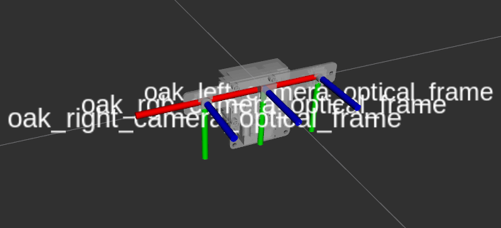
      In this case, it seems that the json file is giving a -7.5 cm(? since no unit is provided) in the x direction from the left camera to the right camera. However, using the drawing provided by you and the assumptions the optical frames are similar to the image provided above it should be positive 7.5 cm?

      Moreover, by plotting the acceleration while moving the camera around I noticed the IMU reference frame has the x pointing upwards, the pointing towards the left camera and the z axis pointing forward (same direction as the z-axis of the optical frame. Making it a left-hand reference frame as opposed to the normal right-hand reference frames mostly used in engineering. Moreover while turning the camera around these principle axes the angular velocity is also captured as if it is a left-hand reference frame. This means that one cannot express the transformation between imu and the cameras using RPY angles only.
      This also means that the translation to the left camera should be positive and not negative as shown in the json file.

      Can you confirm that the IMU has a left hand reference frame as I measured?
      Can you confirm the cameras are using a right hand reference frame?

      Can somebody please provide the actual transformation and reference frames of the 3 cameras and the IMU? I have been searching for weeks now and I have not come close to finding the actual values.

      Also, the functions of the API provided before do not yield results.

      • erik replied to this.

        Hi yuri_durodie ,
        Yes that optical coordiante frame is correct, one thing to note is that CAM_B == LEFT cam (not right), so 7.5cm is correct, as it's on the other side of the board.
        Regarding IMU reference frame - have you applied rotation specified in the json, so both optical and imu coordinate frames are aligned?

        reference frames of the 3 cameras and the IMU

        Extrinsics can be easily calculated, as we have specs on IMU->CAM_B, and also CAM_B->CAM_A and CAM_C->CAM_A. Thoughts?

          erik Thanks for the answer.
          Given your answer I am not sure whether you read or understood what I wrote prior.
          The first issue is that I am pretty sure given the measurements I did that the BMI270 uses a left-hand reference frame. x pointing up, z pointing in the field of view of the cameras, and y pointing to the left camera. While the optical frames of the cameras have a right-hand reference frame. This means you cannot just transform the reference frame of the IMU to align with the optical frames of the cameras using the RPY angles denoted in the .sjon file.
          The second issue is that I am not convinced of the numbers, but I might have to recheck, got a bit paranoid while checking the CAD as proposed previously.

          So in conclusion, can you confirm or refute that the BMI270 imu has a left-hand reference frame?

          Thanks in advance.

          YD

          • erik replied to this.

            @erik and TomMunnecke ,

            Chatgpt is correct and says the same as me. You cannot transfer it using only RPY angles (as provided in the .json file):

            If your IMU has a left-hand coordinate system with coordinates $(x,y,z)$(x,y,z), you can convert it to a right-hand system with the transformation: $(x,y,−z)$(x,y,−z).


            Once you have converted the coordinate systems, you can apply the relative extrinsic parameters (rotation and translation) to align the IMU and the camera.

            Procedure

            1. Convert the IMU coordinates to the right-hand system.

            2. Construct the rotation matrix for pan, roll, and yaw.

            3. Apply the rotation and translation to align the IMU with the camera using the extrinsic matrix.

            Moreover, it also means you have to switch the sign of the angular velocity for the x and y directions. (Which Chatgpt did not mention, but I am sure it will give this information if you ask it specifically.)

            But this is not the actual issue.
            The actual issue is that if the BMI270 is a left-hand reference frame the information provided in the .json file is not enough to calculate the transformation since you need to know that it would be a left-hand reference frame, which is not mentioned in the .json file, which makes me doubt all the information in the .sjon file.

            And since you just confirmed that the IMU uses a left-hand reference frame it means that somebody has to add some additional information to the .json file, and maybe check again all the information.

            I hope you have confirmed this with a person with the actual knowledge to answer the question?
            (I appologise if I am doubting the information you are providing, but your previous answer did not give me a lot of confidence in your abilities for this particular question. )

            • erik replied to this.

              Thansk erik,

              https://discuss.luxonis.com/d/1044-about-oak-d-pro-w-imu-coordinate-system/6 actually confirms left-hand reference frame has been measured by the users as well for the BMI270 (Al the others are talking about the other BNO085 IMU, which seems to have a right-hand reference frame). Although it should have been solved by the 24th of February 2023 according to the post (although it is unclear if the person from luxonis used an oakd pro with a BMI270 IMU) using the ROS API it seems still a left-handed reference frame. and I will correct the data accordingly.

              Cheers and thanks,
              YD