Hello mates,

I am implementing the OAK-D SR PoE cameras in a project where the cameras do measurements for industrial robots. And I have a couple of questions..

1.      What is the plane the camera measures distance to? Is this the outer glass or a sensor which some millimetres behind the glass?

2.      Why does the spatial resolution differs for X and Y axes? https://fov.luxonis.com/ returns me a spatial resolution in X-direction = 3.05 px/mm and in Y-direction = 3.07 px/ mm accordingly.

3.      When I get the depth image, what XY coordinate the central pixel of it corresponds to? Left camera lens centre or right camera left centre or smth else?

4 I have placed two cameras in a way shown on the image (yellow is the FOV). However, what I get from the cameras is a blind space between two cameras instead of a little overlay clearly seen on the images below. What have I done wrong?
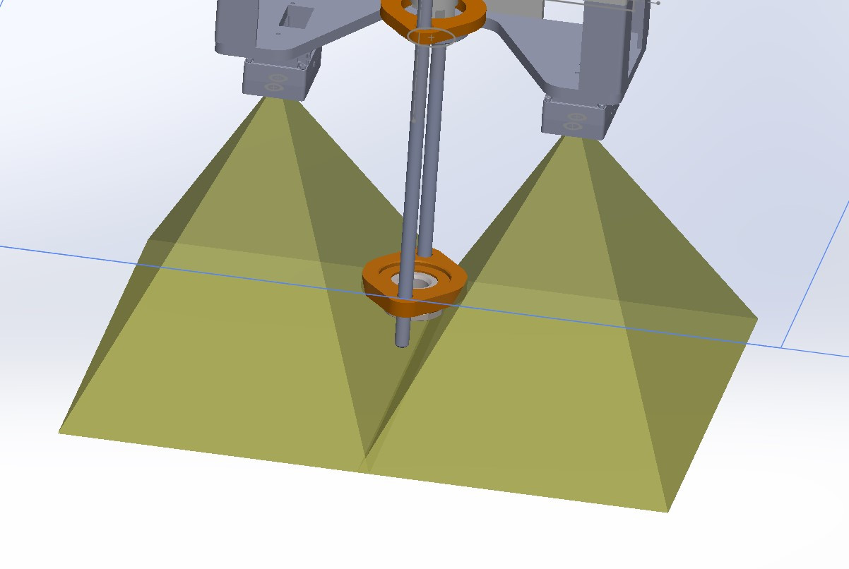
    tu-engineer 1.      What is the plane the camera measures distance to? Is this the outer glass or a sensor which some millimetres behind the glass?

    The sensor (optical center of the sensor).

    tu-engineer Why does the spatial resolution differs for X and Y axes? https://fov.luxonis.com/ returns me a spatial resolution in X-direction = 3.05 px/mm and in Y-direction = 3.07 px/ mm accordingly.

    Depends on what you put in the calculator.

    tu-engineer When I get the depth image, what XY coordinate the central pixel of it corresponds to? Left camera lens centre or right camera left centre or smth else?

    Default is left, but can be changed by stereo.setDepthAlign()

    tu-engineer 4 I have placed two cameras in a way shown on the image (yellow is the FOV). However, what I get from the cameras is a blind space between two cameras instead of a little overlay clearly seen on the images below. What have I done wrong?
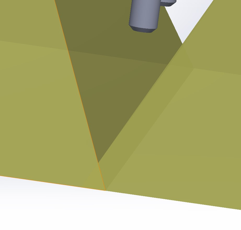
    If you wish to calculate depth, the FOVs need to overlap. Not sure what you mean by blind space.

    Thanks,
    Jaka

      Thank you very much for your message, Jaka!

      jakaskerl The sensor (optical center of the sensor).

      Where is it in regard to the outer glass (or to the housing) ? It is not drawn on blueprints, as for example Realsensce explicitly does. That is why I am asking…

      jakaskerl Depends on what you put in the calculator.

      Put exactly the numers that are listed in specs for this camera on Luxonis website. Btw in the example screenshot provided from Luxonis for this calculator the spatial resolutions for X and Y axes defer as well

      jakaskerl If you wish to calculate depth, the FOVs need to overlap. Not sure what you mean by blind space.

      Yes, what i basically wish - is a single picture consisted of two overlayed depth maps. The overlay is easy but the problem is what I called blind space - I showed it on the scheme below (it looks like either the cameras installed to far away which is not true - see pictures attached previously or FOV is narrower than stated)

      jakaskerl If you wish to calculate depth, the FOVs need to overlap. Not sure what you mean by blind space.

      I have just checked, FOV seems to match specs, I got 258 mm vertical FOV (installation distance 250 mm from camera glas to a plane surface), which is close to 260,28 from Luxonis calculator. I guess, the 3D model of the housing Luxonis has on github is not correct or not up to date (upload date last year). Well, the model looks even slightly different from what I hold in my hands. Is there a newer version of CAD-files available?

        tu-engineer
        The 3D model did not change. If FOV (measured) is as stated in the docs, then I guess the calculations are wrong, or the 3D model width is not correct which would be very strange.

        Thanks,
        Jaka

          jakaskerl

          Thanks for your thoughts! I have checked the CAD files once again, everything appears to be absolutely precise. I have taken FOV= 80x55 deg (you see it in yellow on the pictures I have attached previously) and the STEP model of the camera, which Luxonis has on githab. I place to cameras in a way when their FOV slightly overlap (approx 10 mm) as shown on my sketch. It resulted in a distance of 250 mm between the camera holes.

          Regarding the model - well, it looks pretty much different in comparison with what I bought from Luxonis-authorized supplier in Germany. Could you kindly take a look?

            tu-engineer
            Hm, it looks to me like the camera positions are slightly shifted, which could cause the error you are experiencing.

            Thanks,
            Jaka

              jakaskerl

              You mean the camera positions are shifted on my assembly model, right? i.e. the distance should be less than 250 mm? How have you came to this conclusion? Could you kindly provide your calculations?

                tu-engineer
                I'm merely observing that the camera cones on the 3d model do not align with the cameras on real SR-POE. They seem to be shifted more towards the middle, which could be the cause of the error.

                Thanks,
                Jaka

                  jakaskerl

                  fov cone is aligned to the centre of one of the cameras, from which I receive the image and to which my depth is aligned to

                    jakaskerl

                    Could you kindly elaborate of what you just say? I.e. Where than should it be? It is a bit hard to derive what you are willing to say from the fragmented answers you provide. Thank you anyways!

                    Btw - from the sketch I have provided earlier you can see that the blind zone is located in Y direction. For better understanding, please take a look at the sketch below (red is the camera my fov are centered to and from which I get the images from). In setup the cameras installed in a way, in which they should produce an overlap in Y direction, not a gap.

                      tu-engineer

                      tu-engineer Btw - from the sketch I have provided earlier you can see that the blind zone is located in Y direction

                      Oh, I see, then disregard my previous message.

                      From what I have seen, it can be:

                      1. wrong height from the observed plane
                      2. wrong width between the devices
                      3. wrong HFOV.
                      1. The optical center is incorrectly placed (not accurate enough) or height is incorrect (doubt it).
                      2. doubt it
                      3. I was under the impression you measured the VFOV of the camera, but can't find the message right now. So perhaps I was wrong. Which script are you using to capture frames?
                        Not all outputs of the color camera have to full FOV. 800p should be the full FOV at 16:10 aspect ratio, meanwhile the 720P is 16:9, which cuts the VFOV. Can you check?

                      Thanks,
                      Jaka