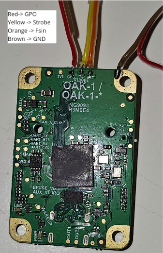
We are trying to sync via HW an OAK-1 camera (IMX378, AF) with a flash lighting.
We opened the enclosure and connected the STROBE and FSIN test pads on the PCB to an oscilloscope, as shown below:

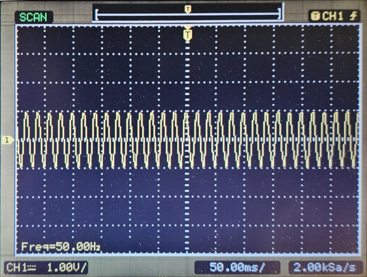
Following the docs, we first attempted to measure the Strobe Signal against GND. Unfortunately, we only observed a noisy 50Hz line signal, even though the camera was on and capturing frames. Note: oscilloscope probe was previously tested and worked fine.

After some research, we couldn't find the schematic due to proprietary hardware constraints. However, we did find a schematic for these signals from another camera on this thread, but it didn't help.
We also tried adding a pull-up resistor and attempted to locate an isolated ground without success.
After all this work, we have some doubts:
Does this hardware have an interface that isolates these signals? If so, where should we get the isolated GND from?
What is the voltage range for the FSIN input?
What is the GPO pin for?
Do we need to configure the camera on software to activate the strobe signal or the FSIN input?
Thanks for your assistance,
Alan