Hi,
I have been able to sync my two AR0234 cameras by setting their frame sync mode to input and connecting their XVS pin to my GPIO41. I have used a small script from the forum to generate a pulse each 50ms, and now they are synced and running at nearly 20Hz. Because of the nature of the sleep function, I have to guess the required sleep time and have no guarantee, that I will sleep the same amount for each time. Does the VPU provide a hardware timer, that can be accessed by the script node? Or is there something else, that can create a precise trigger signal, without additional hardware?

I did try the setStrobeExternal method with GPIO41, but cannot see any strobe signal. I first thought this could be the solution, to generate a trigger signal. And if I use the setStrobeSensor method, the device returns `Fatal error 'DrvGpio' '326'`. (I am using an FFC-3P DM1090FFC R1M0E1 with depthai-core 2.24.0)

    Hi @erik,
    thanks for your reply. I actually did not see that post. Just to be sure, if I connect COM_AUX_IO2 to XVS on my two Arducam AR0234, I will be able to see a trigger signal with my oscilloscope, without the need to call setFrameSyncMode(dai::CameraControl::FrameSyncMode::INPUT) when I create the pipeline?

    Maybe I should provide more side informations about my use cases:

    1. I have two FFC-3P, each one with two AR0234 cams. I need a synced point cloud, that's why I thought of a trigger signal that I can route to all four AR0234 cams.
    2. I have one FFC-3P with two AR0234 and a laser beam, that should only emit light on every second frame. If I have a trigger signal, I can easily toggle the laser.

    Hi @VisiCon-Philip ,
    I think in that case each FFC-3P will try to generate their own signal - do you have osciliscope to verify that? If that is the case, then you could set the fsync mode to input, so one FFC-3P won't try to generate fsync signal.

    @erik I did not measure any trigger signal with the following setup:

    1. XVS and COM_AUX_IO2 are connected by the violet and thin green wire.
    2. The yellow wire measures SIOC on the AR0234, which is a clock that is running after the exposure. I use this to verify that an image has been taken.
    3. R14 has been removed from the FFC-3P, which means that COM_AUX_IO2 is not connected with FSIN1, FSIN2 and FSIN3. I did this manually with step 1.


    You can see on the oscilloscope that something is happening every 25ms on the camera (yellow plot), but there is no trigger signal (cyan plot). The thin green wire is definitely connected to COM_AUX_IO2, because if I manually create a trigger signal using a script node and GPIO41, I can measure it. For me, it looks like COM_AUX_IO2 is not initialized and just showing some interference.

    Code snippet:

    #include "depthai/depthai.hpp"
    
    #include <iostream>
    
    uint64_t numImages[2] = {0, 0};
    
    void onFrame(const int camId)
    {
    	numImages[camId]++;
    }
    
    int main()
    {
    	dai::Pipeline pipeline;
    	auto camLeft = pipeline.create<dai::node::ColorCamera>();
    	auto camRight = pipeline.create<dai::node::ColorCamera>();
    	auto xoutLeft = pipeline.create<dai::node::XLinkOut>();
    	auto xoutRight = pipeline.create<dai::node::XLinkOut>();
    
    	xoutLeft->setStreamName("left");
    	xoutRight->setStreamName("right");
    
    	camLeft->setBoardSocket(dai::CameraBoardSocket::CAM_B);
    	camLeft->setResolution(dai::ColorCameraProperties::SensorResolution::THE_1200_P);
    	camLeft->setIspScale(2,3);
    	camLeft->setFps(20);
    	camLeft->isp.link(xoutLeft->input);
    	camLeft->initialControl.setManualExposure(1000, 100);
    
    	camRight->setBoardSocket(dai::CameraBoardSocket::CAM_C);
    	camRight->setResolution(dai::ColorCameraProperties::SensorResolution::THE_1200_P);
    	camRight->setIspScale(2,3);
    	camRight->setFps(20);
    	camRight->isp.link(xoutRight->input);
    	camRight->initialControl.setManualExposure(1000, 100);
    
    	dai::Device device(pipeline, dai::UsbSpeed::SUPER_PLUS);
    	auto qLeft = device.getOutputQueue("left", 2, false);
    	auto qRight = device.getOutputQueue("right", 2, false);
    	qLeft->addCallback([](){ onFrame(0); });
    	qRight->addCallback([](){ onFrame(1); });
    
    	while(true)
    	{
    		std::this_thread::sleep_for(std::chrono::seconds(2));
    		std::cout << "Got " << numImages[0] << " and " << numImages[1] << " images" << std::endl;
    	}
    	return 0;
    }

    Hi @VisiCon-Philip ,
    My bad, I was wrong - in my case (linked above), I2C is shared between CAM_B and CAM_C, so both sensors get the "start frame" command via I2C at the exact same time, and therefor are "synced". With 2 OAK-FFCs this wouldn't work.

    You can toggle FSYNC manually within script node on one FFC-4P, and then all AR0234 cams should have FSYNC to input.
    Demo script:

    from depthai_sdk import OakCamera
    import depthai as dai
    
    FPS = 30
    with OakCamera() as oak:
        left = oak.create_camera('CAM_B', fps=FPS)
        right = oak.create_camera('CAM_C', fps=FPS)
        # Set colorCameras FSYNC mode
        left.node.initialControl.setFrameSyncMode(dai.CameraControl.FrameSyncMode.INPUT)
        right.node.initialControl.setFrameSyncMode(dai.CameraControl.FrameSyncMode.INPUT)
    
        script = oak.pipeline.createScript()
        script.setProcessor(dai.ProcessorType.LEON_CSS)
        script.setScript("""
            import time
            import GPIO
            # Script static arguments
            fps = %f
            calib = Device.readCalibration2().getEepromData()
            prodName  = calib.productName
            boardName = calib.boardName
            boardRev  = calib.boardRev
            node.warn(f'Product name  : {prodName}')
            node.warn(f'Board name    : {boardName}')
            node.warn(f'Board revision: {boardRev}')
            revision = -1
            # Very basic parsing here, TODO improve
            if len(boardRev) >= 2 and boardRev[0] == 'R':
                revision = int(boardRev[1])
            node.warn(f'Parsed revision number: {revision}')
            # Defaults for OAK-FFC-4P older revisions (<= R5)
            GPIO_FSIN_2LANE = 41  # COM_AUX_IO2
            GPIO_FSIN_4LANE = 40
            GPIO_FSIN_MODE_SELECT = 6  # Drive 1 to tie together FSIN_2LANE and FSIN_4LANE
            if revision >= 6:
                GPIO_FSIN_2LANE = 41  # still COM_AUX_IO2, not PWM capable
                GPIO_FSIN_4LANE = 42  # also not PWM capable
                GPIO_FSIN_MODE_SELECT = 38  # Drive 1 to tie together FSIN_2LANE and FSIN_4LANE
            # Note: on R7 GPIO_FSIN_MODE_SELECT is pulled up, driving high isn't necessary (but fine to do)
            # GPIO initialization
            GPIO.setup(GPIO_FSIN_2LANE, GPIO.OUT)
            GPIO.write(GPIO_FSIN_2LANE, 0)
            GPIO.setup(GPIO_FSIN_4LANE, GPIO.IN)
            GPIO.setup(GPIO_FSIN_MODE_SELECT, GPIO.OUT)
            GPIO.write(GPIO_FSIN_MODE_SELECT, 1)
            period = 1 / fps
            active = 0.001
            node.warn(f'FPS: {fps}  Period: {period}')
            withInterrupts = False
            if withInterrupts:
                node.critical(f'[TODO] FSYNC with timer interrupts (more precise) not implemented')
            else:
                overhead = 0.003  # Empirical, TODO add thread priority option!
                while True:
                    GPIO.write(GPIO_FSIN_2LANE, 1)
                    time.sleep(active)
                    GPIO.write(GPIO_FSIN_2LANE, 0)
                    time.sleep(period - active - overhead)
        """ % (FPS))
    
        oak.callback([left, right], lambda packets:
                     print(f"Left {packets['CAM_B_video'].msg.getTimestamp()}, Right {packets['CAM_C_video'].msg.getTimestamp()}")
                     ).configure_syncing(enable_sync=True)
    
        oak.start(blocking=True)

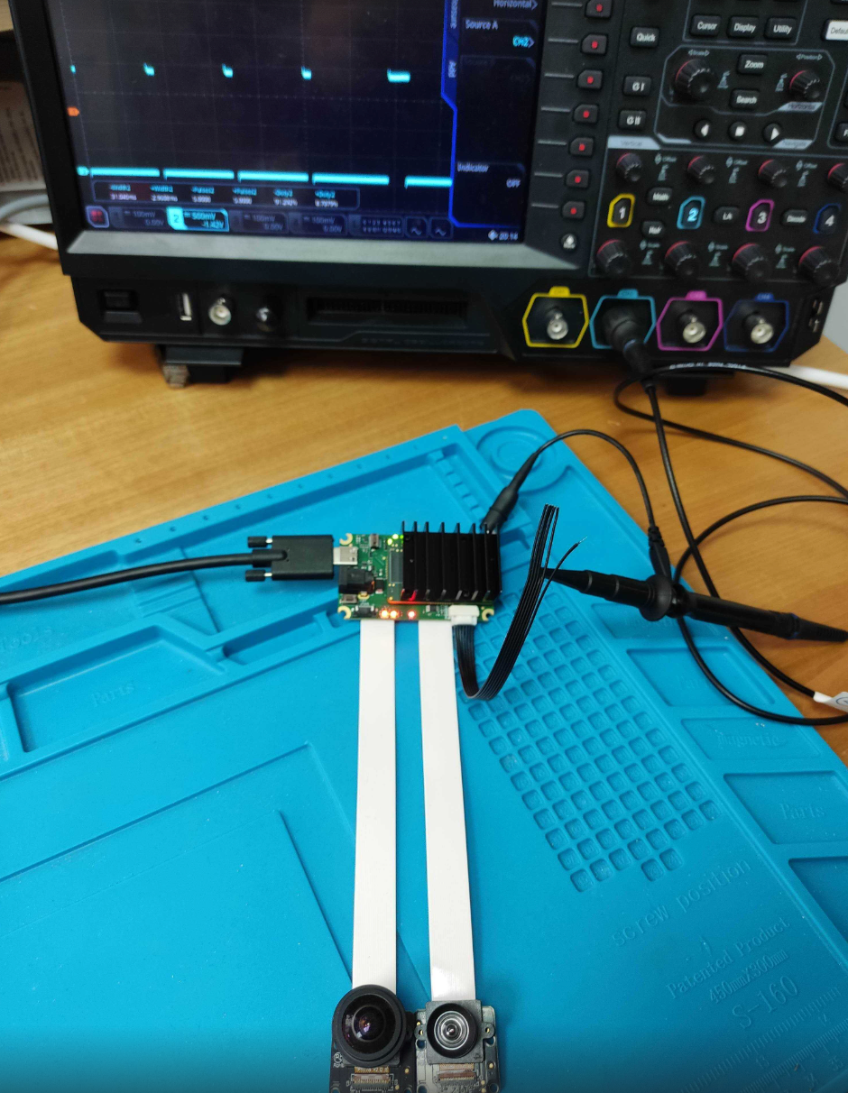
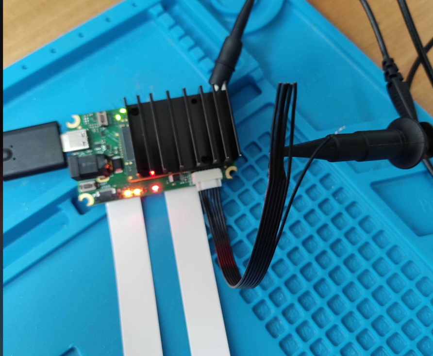
    Script above running on FFC-4P with 2x FFC-AR0234 connected and I'm measuring FSYNC via PSRBS connector:
    @erik Toggling GPIO 41 manually is exactly what I am using currently, as mentioned in my first post. So you are planning to implement timer interrupts sooner or later?

    I will measure the standard deviation of the time between two trigger signals while the VPU does some stereo block matching, to evaluate if the timing is precise and reliable enough, or if I need an external trigger e.g. microcontroller.

    a month later

    @VisiCon-Philip @erik

    It is my goal as well to hardware sync the AR0234 sensors, and I guess I would have to set Fsync manually within the script node, so they can all be set to input. Then use the PSRBS cable to drive the FSIN 4 lane line with the pwm signal to drive the fps.

    Is my understanding correct and are there any known bugs, or should this work to hardware sync multiple AR0234 sensors from Arducam using the XVS pin and wire them together between all the sensors?

    I have hardware syncing working with the OV9782 color global camera modules and it works really well, but the camera board had the FSIN pin unlike the AR0234 which has the XVS. I believe they should operate the same, are there any differences to be aware of?

    Hi @Nearpoint ,
    Besides not being connected via cable (can be fixed by manually soldering wire from XVS to the FSYNC test pad on the cable), AR0234 also doesn't generate FSYNC signal like OV9782 does. So you'd need to generate it manually - either externally, or via Script node.

      erik

      Ah well my plan is to drive the signal externally for precise accurate timing, using the teensy 4.0 microcontroller which is more precise than the arduino for pwm signal generation. Then using the PSRBS cable I can drive the FSIN 4 lane pin.

      As for wiring the AR0234 sensor, could I connect the XVS pins with each other instead of to the test pad? And then set the frame sync to input for all the sensors since I am driving it externally? Is my logic clear here, will this work?

      • erik replied to this.