Dear Luxonis Hardware Experts,

We have the need of hardware syncing of multiple OAK FFC 4P based stereo cameras and we do not know when the FSYNC Y adapter would be released. Therefore, we would like to prototype ourselves the adapter for purpose of daisy-chaining : there would be one camera acting as master providing trigger signal, other acting as slaves.

However, I am not quite clear about the functionality of the GPIO3 in the following description of the BNC to M8 adapter :

We made our own BNC to M8 adapter by splitting one BNC to BNC cable and one M8 to M8 cable. We then used that to connect the signal generator (BNC) to the FSYNC Y-adapter (M8).

The signal line (BNC core) has to be connected to pin 1 of the M8 cable (FSYNC line). GND from the BNC connector (so the shielding around it) has to be connected to both pin 3 (GPIO3/5V) and pin 8 (GND) of the M8 cable. If GPIO3 is not connected to the ground, the camera on the first FSYNC Y-adapter won’t work, only the cameras after it will be synced together. This is because the first FSYNC Y-adapter will pull the GPIO3 to GND, as seen in the schematics below.
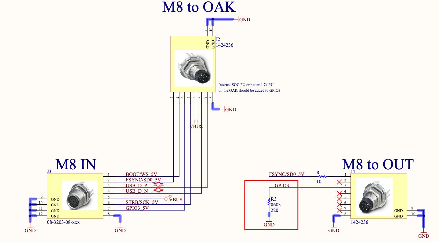
I would like to know if the GPIO3 is used to detect by the connected OAK camera in order to identify itself as master or slave ?

Thanks in advance and best regards,
Khang

Hi @l4es ,
I believe ETA for Y-adapter is in ~ January, but I am not sure how useful that would be for you as the FFC-4P doesn't have M8 connector. So for you likely it'd be easier to just connect a all FSYNC lines with a wire directly. And you are right, GPIO3 is used to detect whether the device should be FSYNC master or slave (if it's not pulled down, it means it is the first in the daisy chain and should be master), and it's all done in FW. Thoughts?
Thanks, Erik

  • l4es replied to this.

    Hi erik ,

    Thanks for your clarification. I designed an adapter board from the PSRBS connector on the FFC-4P to an M8 connector like this :

    It is mostly for purpose of re-directing the COM_AUX_IO2 / FSIN from the PSRBS connector to the M8 connector with certain opto-isolation.

    However, seeing that the master/slave detection is done in the firmware via a similar GPIO, I think my adapter would only work in the fixed/hard-wired master (with the triggering signal from COM_AUX_IO2) or slave mode where all the cameras would be triggered externally as we cannot touch your firmware for the auto-detection.

    Best Regards,
    Khang

    Hi @l4es ,
    That's cool! This auto-detection system is mostly for convenience, if you already know which mxid should be master you can also just set the FSYNC mode manually in the code, via

    # Some sensor on the cam you want to drive the fsync
    cam1sensorX.initialControl.setFrameSyncMode(dai.CameraControl.FrameSyncMode.OUTPUT)
    # all other sensors on all cameras
    cam2sensorX.initialControl.setFrameSyncMode(dai.CameraControl.FrameSyncMode.INPUT)
    • l4es replied to this.

      Hi erik,

      By the way, I wonder if we could do some check on a dedicated GPIO (with GPIO.read() for example) for the detection of master/slave in the Script node?

      Best Regards,
      Khang

      Hi @l4es
      Perhaps, the COM_AUX_IO2 is connected to IO13 on the FFC-4P, I think it'd be best to try it out. I'm a bit skeptical, as it might break original function of the pin.

      • l4es replied to this.

        Hi erik ,

        Thanks for your reply. I just realized that there's not other GPIO than COM_AUX_IO2 accessible from outside of the OAK FFC 4P board. However, in our current use-case, COM_AUX_IO2 is used to trigger the AR0234CS sensors on the OAK-FFC-AR0234-M12 modules.

        Maybe you suggestion will work with the OAK-FFC-OV9282 modules as one of them can generates the trigger signals to other sensors of the same camera and of other cameras.

        Best Regards,
        Khang