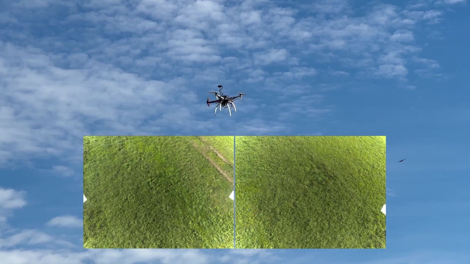
We bolted an OAK4 FFC onto an off-the-shelf F450 quadcopter, added two global-shutter cameras and an off-the-shelf barometric sensor, and flew it. This post walks through the whole build: the parts, every bolt, the wiring, and the software that turns it into a flying edge-AI camera.
Why put an OAK4 FFC on a drone?
A drone payload has three hard limits: weight, power and radio bandwidth. The OAK4 FFC helps with all three. It is a lightweight bare board, it runs straight off the flight battery, and it is powerful enough to run AI right on board, so you send results down to the ground instead of raw video.
That opens the door to smarter, more autonomous flight, with the drone processing what it sees in real time.
In our build the board drives two cameras pointing down at the ground and reads a pressure sensor over I²C to track altitude. The mount is 3D-printed for the F450. Your drone will need a different mount, but the wiring stays the same.
Bill of materials
Everything we used, grouped by where it goes. Quantities are for one drone.
Drone platform
Vision payload
- 1× OAK4 FFC (Kit or barebones): RVC4 baseboard, 6–32 V DC input
- 2× OG05B10 fixed-focus camera module (OAK-FFC OG05): global shutter, 2592 × 1944 at 30 fps in our app, on CAM_D and CAM_E
- 2× camera ribbon (FFC) cable: included with the camera modules
- 1× SparkFun Pressure Sensor – BMP581 (Qwiic): barometric pressure and temperature over I²C, address 0x47
- 1× Qwiic-to-2 mm header cable: Qwiic (4-pin JST-SH) on the sensor end, 2.0 mm-pitch header on the board end, wired to the OAK4 FFC I²C pinout
- 1× 2 mm-pitch socket header, 16-pin (2 × 8), Würth Elektronik WR-PHD 62001621821: the board end of the sensor cable
- 1× DC power cable: included in the OAK4 FFC Kit; build your own for barebones
Mount and fasteners
- 1× 3D-printed F450 payload mount and camera module holder (STEP files attached in step 1)
- 10× M2.5 threaded inserts, pressed into the printed mount
- 4× M2.5 × 10 mm standoffs, carrying the OAK4 FFC board
- 4× M2 × 10 mm standoffs, carrying the camera modules
- 4× M2.5 × 10 mm bolts, camera module holder to mount
- 2× M2.5 × 10 mm bolts, pressure sensor to mount
- 4× M2.5 × 15 mm bolts (included with the board), OAK4 FFC to its standoffs
- 8× M2 × 5 mm bolts, four per camera module
- 2× M3 × 20 mm Allen bolts with 2× M3 lock nuts, mount to the F450 frame
Tools and software
- Soldering iron and heat-shrink, for the power lead
- Hex keys or a small driver with hex bits
- Soldering-iron tip or press tool for the threaded inserts
- OAK Viewer for camera setup and calibration
- An AI agent with the Luxonis Agent Toolkit skills, plus
oakctl to run the app on the device
The build, step by step
Do the hardware with the flight battery unplugged.
1. Prepare the printed mount
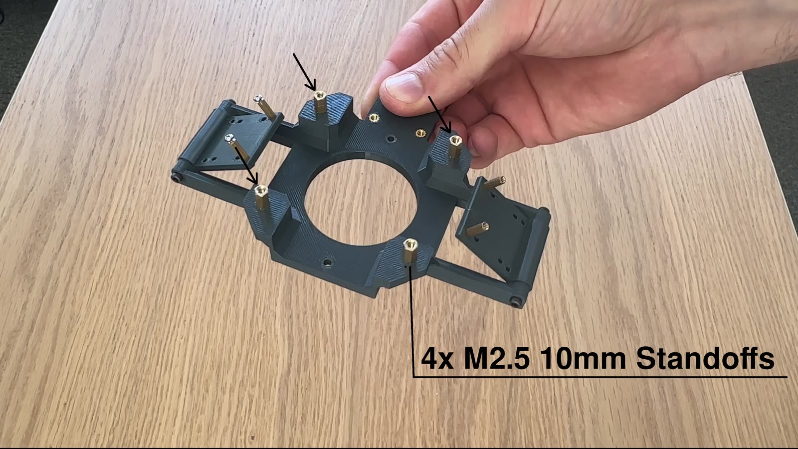
Press the ten M2.5 threaded inserts into the mount. Then screw in four M2.5 × 10 mm standoffs for the OAK4 FFC and four M2 × 10 mm standoffs for the camera modules. Attach the camera module holder with four M2.5 × 10 mm bolts.
Download the STEP files below to print the mount as is, or adapt it to your own frame:
https://drive.google.com/drive/folders/14u54pevwfM3UKsxC39twa7cvF4onkb4t?usp=sharing
2. Bolt the mount to the frame
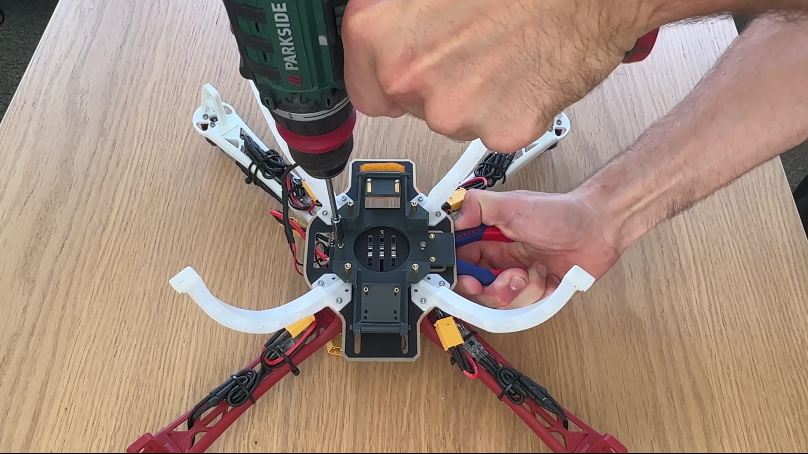
Secure the mount to the underside of the F450 with two M3 × 20 mm Allen bolts and lock nuts. Lock nuts matter here: motor vibration loosens plain nuts quickly.
3. Wire the pressure sensor
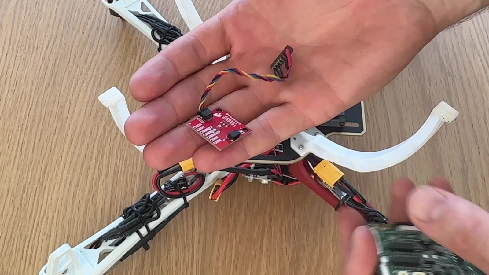
The BMP581 board uses a Qwiic connector; the OAK4 FFC exposes I²C on a 2 mm-pitch header. A short cable with Qwiic on one end and a 2 mm-pitch socket header on the other (Würth Elektronik WR-PHD 62001621821, 2 × 8 pins), wired to the board's pinout, bridges the two. Fix the sensor to the mount with two M2.5 × 10 mm bolts.
We chose the BMP581 because it runs at 1.8 V, the voltage the OAK4 FFC's I²C header puts out. If your sensor needs 3.3 V, add a bidirectional I²C voltage level shifter between the board and the sensor.
Check the pin order against the OAK4 FFC pinout before you power up. The full pinout is in our OAK4 FFC getting started guide. Swapping power and GND is the classic way to kill a sensor.
4. Fit the cameras
We used two fixed-focus OG05B10 modules. Plug in the ribbon cables that come with them, then secure each module to its standoffs with four M2 × 5 mm bolts. Route the ribbons to the connectors on the side of the OAK4 FFC.
The holder lets you tilt the cameras, so you can set the view angle you need before you tighten everything.
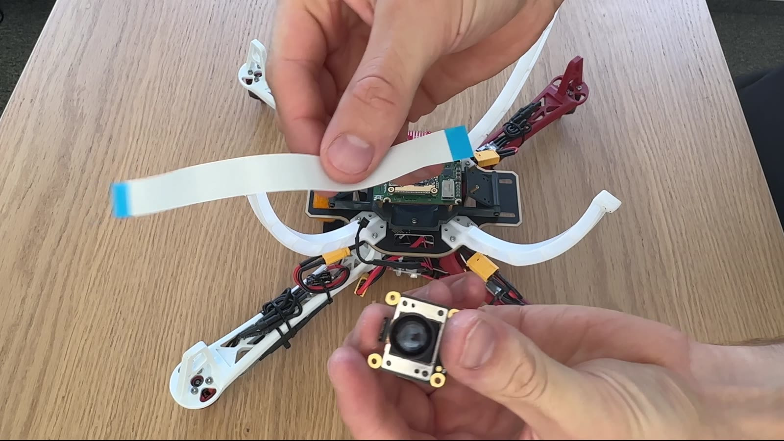
5. Mount the board
Set the OAK4 FFC on its four standoffs and fix it with four M2.5 × 15 mm bolts. These bolts come with the OAK4 FFC.
6. Power from the flight battery
The OAK4 FFC takes 6 to 32 V, so a 3S pack (12.6 V fully charged) powers it directly with no regulator. Solder the power cable to the drone's power leads and plug it into the board's DC connector.
The cable ships with the OAK4 FFC Kit. With the barebones board you make your own; the parts are listed in our OAK4 FFC getting started guide.
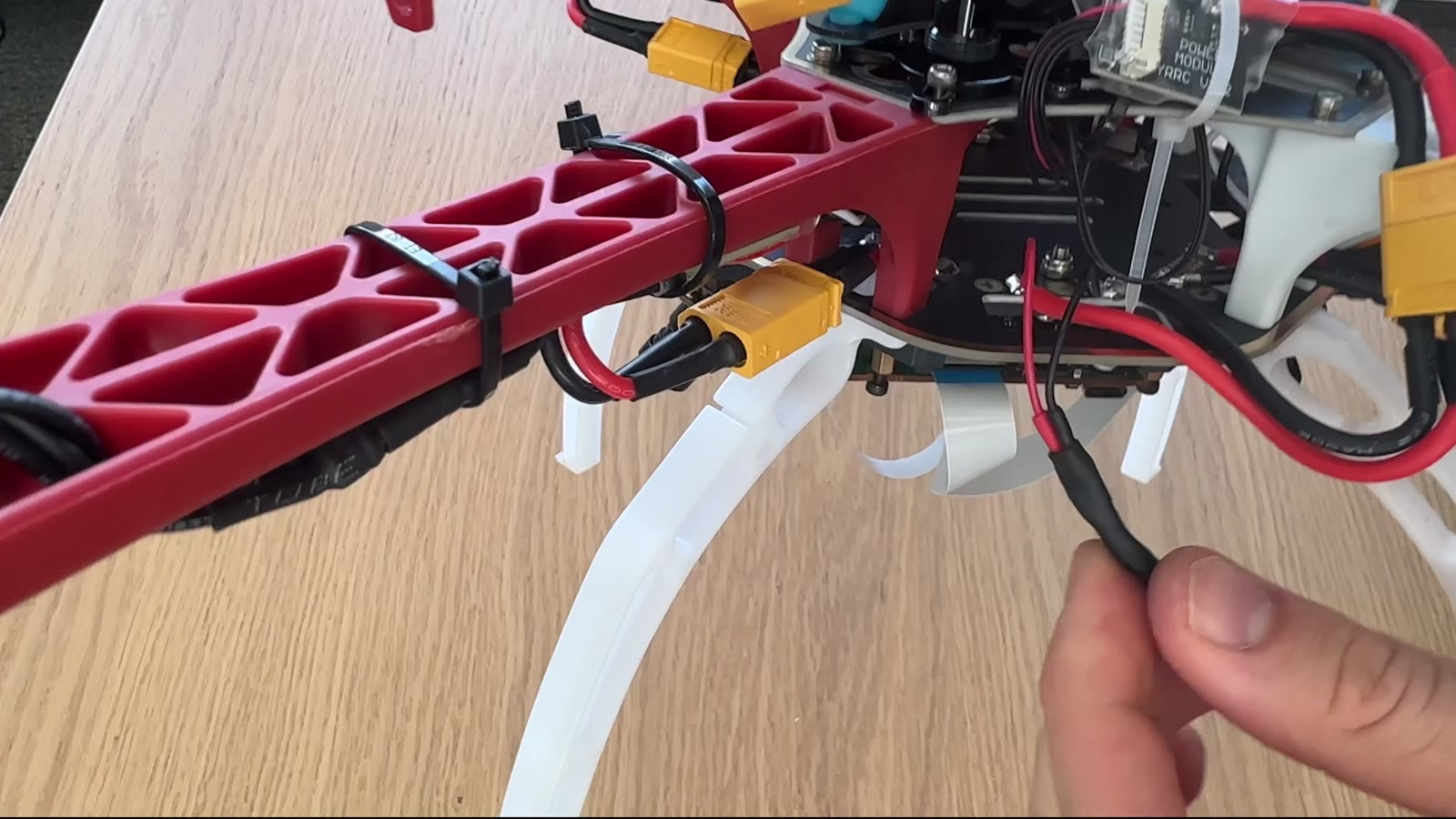
Budget for the extra draw: RVC4 devices peak at about 25 W and average 10–15 W under load, per the OAK4 docs. That is small next to the motors, but it does trim flight time.
The software side
With the hardware done, two jobs remain: tell the system where the cameras sit, and write an app that shows what the drone sees and how high it is.
Camera extrinsics in OAK Viewer
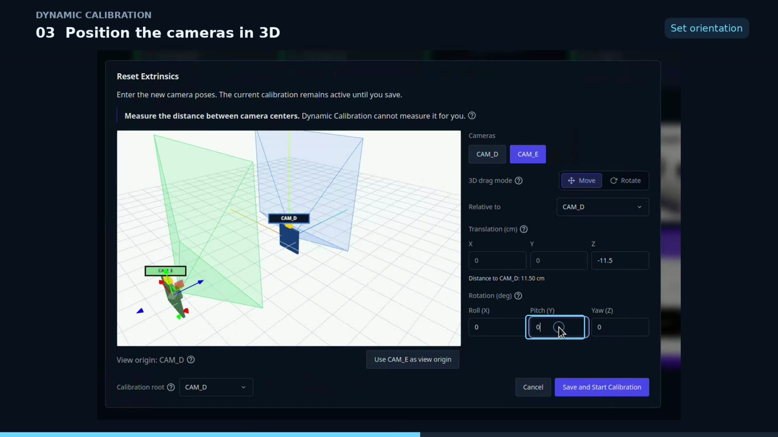
Our two cameras sit 11.5 cm apart and look at different patches of ground, so their views don't overlap. In OAK Viewer we entered their relative positions and rotations by hand: CAM_D as the origin, CAM_E offset along one axis.
For rigs where the views do overlap, Viewer's FFC calibration uses our Dynamic Calibration to refine the extrinsics automatically from live images, with no calibration targets. That is what you want for 3D point clouds or image stitching.
A flight app, built with an AI agent
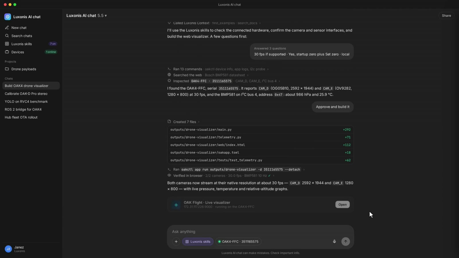
With AI agents and the Luxonis Agent Skills, it's easier than ever to build apps for Luxonis devices. We described what we wanted in plain language. The agent probed the board, found both OG05B10 cameras and the BMP581 on I²C bus 4 at address 0x47, and wrote the app.
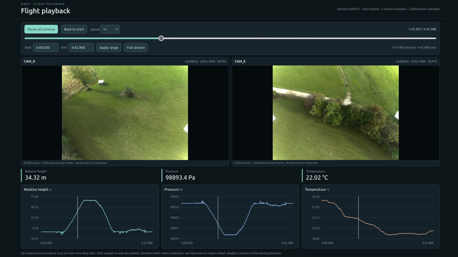
The result is a small OAK app (Python backend, web front end) that runs on the OAK4 FFC itself and is deployed with oakctl app run. It streams both cameras at 2592 × 1944, 30 fps, and reads the sensor at 10 Hz. A flight recorder plays back video and telemetry side by side.
Altitude from pressure
Air pressure drops as you climb, by roughly 12 Pa per metre near sea level. The app zeroes on the pressure at take-off and converts every new reading into height above that point. That makes it a relative altitude, which is what you want for a short flight; slow weather changes will drift it over hours.
In the playback below the drone reached 34.3 m while pressure fell to 98,893 Pa. Temperature from the same sensor is logged alongside.
The BMP581 is just one example. Any compatible I²C sensor can hang off the same bus for your own application.
Build your own
Follow this guide step by step, or adapt it for your own project: a different frame, other camera modules, or extra I²C sensors. The wiring stays the same. New to the OAK4 FFC? Start with the getting started guide.
Downloads and links
The video points readers here for these.
Built something on top of this? Share it with us on the Luxonis forum.