TL;DR: Luxonis stereo cameras now come with factory calibration that aligns the cameras, IMU, and device housing into one shared coordinate system. This compensates for real-world manufacturing tolerances, making it much easier to combine camera and IMU data, align point clouds with the physical device, and integrate cameras into robots. Validation showed the new calibration reduces camera-to-IMU alignment error from about 1.16° to 0.38°, providing significantly more consistent sensor fusion out of the box.
Luxonis cameras are packed with sensors, each device carrying an IMU and anything between one to three RGB/Monochrome cameras, sometimes even topped-off with a Time-of-Flight sensor. Eachof these sensors measures data from its own individual point-of-view, its own coordinate system. What happens, however, when we want to relate these measurements to the real world? That's where our robots, manipulators, vehicles live and they need to put all the data from the sensors into a world coordinate system.
Going from the sensor to the world has always been a missing link in Luxonis devices. Not anymore!
But how do we go from the sensor to anything that is physically attached to the outside world? There are only 2 direct links - the gravity vector that we can measure through the IMU sensor and the physical body of the device itself, that we can attach to a known, exact pose, for example using the VESA mount.
Accurate transformation between the housing of the device and the rest of the sensors, including IMU, is the only missing piece of information. And it is precisely what you will get now, for each device from upcoming production.
In theory, all of these coordinate systems are known from the mechanical design of the device. In practice, every assembled device has small production tolerances. Sensors are mounted very accurately, but not perfectly. In addition to that, the IMU sensor carries inherent biases that need to be compensated for. Accurate factory calibration is the key here.
Factory calibration of Luxonis devices has until now focused on the internal alignment of camera sensors with respect to each other. Stereo depth, rectification, spatial AI, and point clouds all depend on accurate camera-to-camera geometry. Now, all Luxonis stereo cameras also undergo factory calibration of the device housing and IMU. This completes the chain such that the cameras, IMU, and physical device bodies all are interconnected through a single, calibrated, geometrical model, all data transferable to the real world around us.
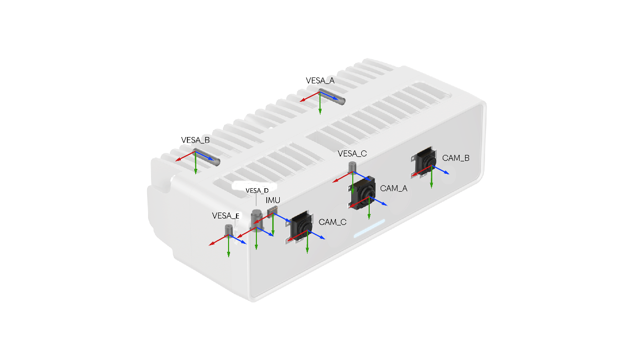
This render shows the device's housing coordinate systems and housing-aligned sensor frames. In the real assembled device, the native sensor coordinate systems can differ slightly from the ideal housing-aligned ones because of normal manufacturing tolerances. That small offset is exactly why factory calibration is needed: it measures the real relationship between the native sensor frames and the housing-defined frames.
Why does this matter?
Imagine mounting a camera on a robot using its VESA mount. The robot knows exactly where the mount is, but the sensors inside the camera aren't perfectly positioned according to the CAD model.
Manufacturing is incredibly precise, but not perfect. Every assembled device has tiny differences caused by production tolerances. The IMU also introduces small measurement biases that vary from device to device.
These differences are small—often fractions of a degree—but they're large enough to matter when building accurate robotics, mapping, or visual-inertial systems.
Factory calibration measures these real-world offsets for every device individually.
The result is a complete calibration chain connecting:
- every camera,
- the IMU,
- and the physical housing of the device.
That means all sensor data can now be accurately related to the outside world.
Two kinds of coordinate systems
Luxonis devices expose two groups of coordinate systems.
The first are the native sensor frames:
These represent the coordinate systems in which each sensor naturally measures data.
The second are housing coordinate systems, which are tied to the physical device body:
- mounting locations (such as VESA mounts),
- front-cover reference frames,
- housing-aligned sensor frames.
These are useful whenever you care about the camera as a physical object rather than just a collection of sensors.
One important distinction is between a native sensor frame and its housing-aligned counterpart.
For example:
- CAM_A is the camera's native optical frame.
- Housing.CAM_A shares the same origin, but its axes are aligned with the housing.
The same applies to:
Both share the same physical location, but their orientations may differ slightly after manufacturing.
Factory calibration measures that difference.
If you want the full list of available coordinate systems, their meaning, and the current API for retrieving transforms between them, the best reference is the official DepthAI documentation: “Coordinate Systems”
Why not just use the CAD model?
In theory, the position of every sensor is already known from the mechanical design.
In reality, every assembled device is slightly different.
Even tiny assembly tolerances accumulate, meaning the real sensor orientations differ slightly from the ideal CAD model. Without measuring these offsets, all downstream applications inherit that error.
Factory calibration removes this uncertainty by measuring the actual geometry of every device.
One common reference frame
Once housing and IMU calibration are available, every measurement can be expressed in the same physical coordinate system.
For example:
- a camera detects a 3D point,
- the IMU measures gravity,
- the robot knows the camera's mounting position.
Instead of each existing in its own coordinate system, they can all be transformed into a common housing frame.
That makes many applications significantly easier.
- Robotics - Relate sensor data directly to the physical mount
- Visual-Inertial Odometry (VIO) - Use camera and IMU measurements consistently
- Sensor Fusion - Combine multiple sensors in one frame
- Calibration Validation - Compare independent measurements directly
The key idea is simple:
Luxonis cameras are no longer just calibrated stereo pairs—they are calibrated physical sensor systems.
Using housing transforms in DepthAI
DepthAI exposes the calibrated transforms directly.
Applications can request transforms between camera coordinate systems and housing coordinate systems.
For example, a transform can be retrieved from CAM_A to VESA_A, allowing points measured by the camera to be expressed directly relative to the mounting interface.
Many nodes can also work directly in housing coordinate systems.
The PointCloud node, for example, can generate point clouds in either camera coordinates or any supported housing coordinate system. Instead of transforming every point afterward, the desired output frame can simply be selected.
The IMU follows the same idea.
Requesting:
ACCELEROMETER_UNCALIBRATED GYROSCOPE_UNCALIBRATED
returns measurements in the native IMU frame.
Requesting:
ACCELEROMETER_CALIBRATED GYROSCOPE_CALIBRATED
applies the calibration corrections, producing data aligned with the housing frame (Housing.IMU).
Validating the calibration
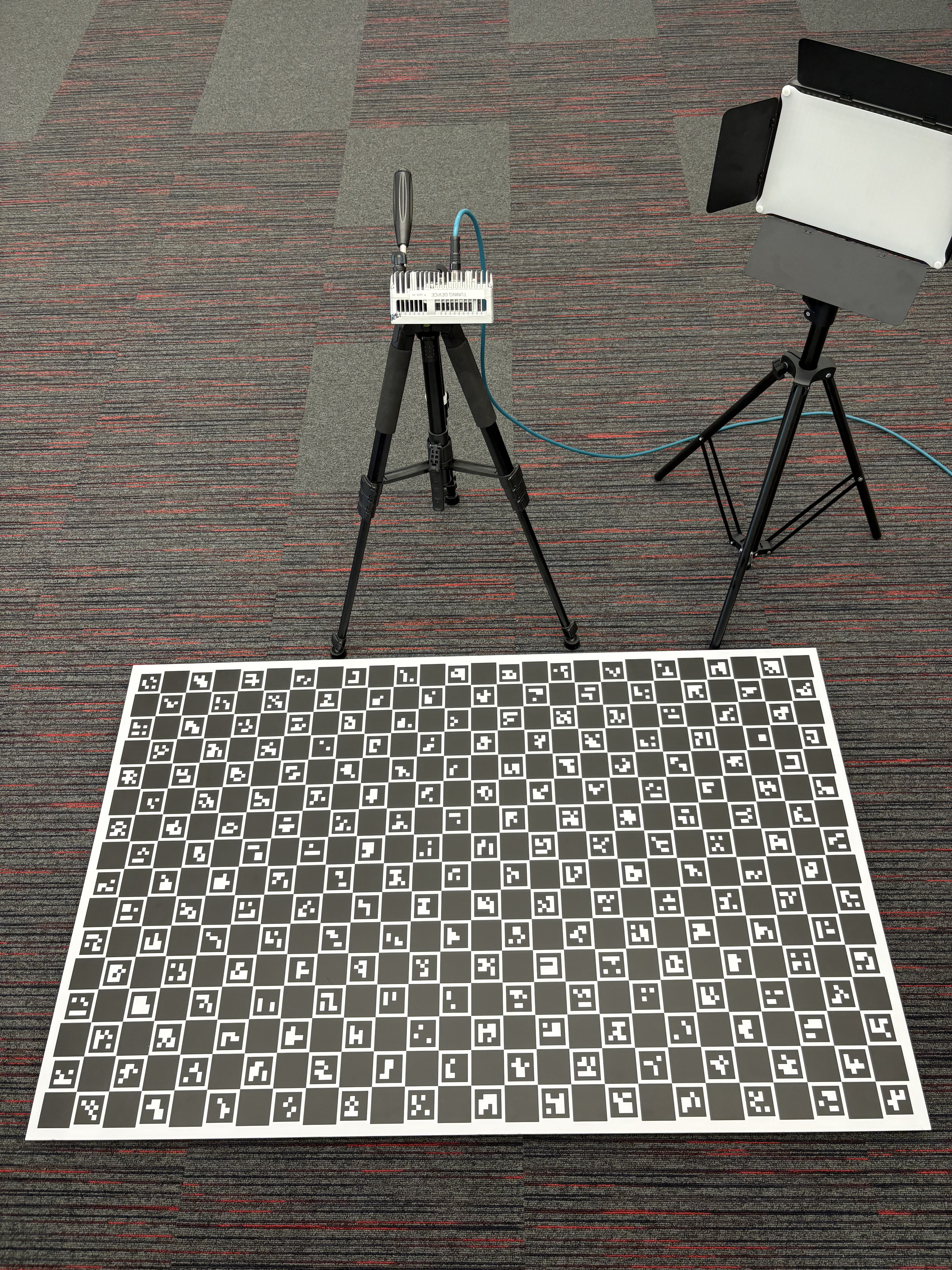
To verify that the complete calibration chain works in practice, we performed a ChArUco-to-IMU gravity alignment experiment.
The goal wasn't simply to inspect calibration values—it was to check whether two completely independent sensors agreed about the real world.
The experiment worked like this:
- A ChArUco board was placed flat on the floor.
- The camera estimated the board's pose.
- From that pose, we computed the board's normal vector.
- The IMU measured the gravity vector.
- Both vectors were transformed into
Housing.IMU.
- We measured the angle between them.
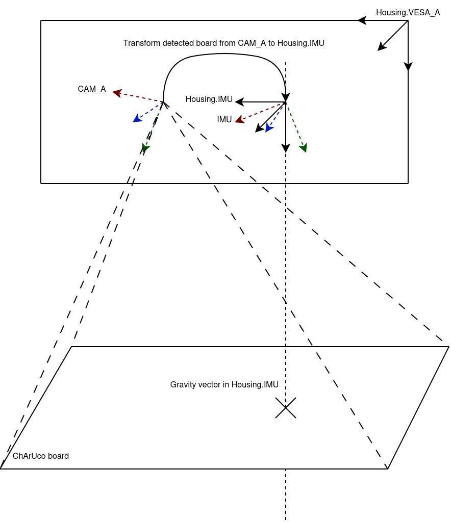
Since the board lies flat on the floor, its normal should point in the same direction as gravity.
If the calibration is accurate, those two independently measured vectors should closely align.
This provides an end-to-end validation of the entire calibration chain rather than testing the camera and IMU separately.
Each device was tested using:
- a ChArUco board on the floor,
- a camera viewing it at roughly 45°,
- gravity measurements from the IMU,
- 100 samples for every configuration.
Results
On one OAK-4-PRO device:
- Uncalibrated camera + uncalibrated IMU - Mean Error: 1.16°
- Fully calibrated camera + calibrated IMU - Mean Error 0.38°
Across five RVC4 devices, the average deviation after fresh reference camera calibration was also approximately 0.38°.
The improvement isn't just a smaller number.
It shows that the camera and IMU now describe the same physical world much more consistently.
That's exactly what applications such as robotics, mapping, visual-inertial odometry, and sensor fusion rely on.
At this point, much of the remaining error comes from the measurement setup itself rather than the calibration, making this a strong validation of the complete multi-sensor calibration pipeline.
Conclusion
With factory calibration linking the cameras, IMU, and housing, Luxonis stereo cameras become unified physical sensing systems rather than independent sensors packaged together.
Applications can now confidently combine camera observations, IMU measurements, point clouds, and robot poses in a shared coordinate system tied directly to the physical device.
For robotics, mapping, SLAM, and visual-inertial applications, this removes one of the last missing pieces between sensor measurements and the real world.