• DepthAI-v2
  • Get rectified color images from stereoComponent

Hello, I am running an OAK FFC 4P with two IMX378 color cameras, trying to use this setup as a stereo camera, both for computer vision stuff, and to use it as a teleoperated robot camera. For this last use, I would need to be able to get both left and right color rectified frames.

Using this piece of code I was able to visualize a (very bad) depthmap, the unrectified left and right frames (in color) as well as the rectified left and right frames, but in grayscale. How can I get the rectified frames in color ?

from depthai_sdk import OakCamera
oak = OakCamera()
camA = oak.create_camera('cama,color', resolution='800p', fps=30)

camD = oak.create_camera('camd,color', resolution='800p', fps=30)
stereo = oak.create_stereo(left=camA, right=camD)
oak.visualize([stereo.out.disparity, camA, camD, stereo.out.rectified_left, stereo.out.rectified_right], fps=True)
oak.start(blocking=True)

As for the depthmap, I need to check that my calibration is correct

Another issue I am having is that about 10minutes ago, this script stopped working, without changing anything. It just hangs without displaying any images. I have tried unplugging the board and rebooting my computer, but it did not help. I will try reinstalling the depthai libraries in a separate virtual environment now.

Thanks !

  • erik replied to this.

    Ok, thanks !

    Would it make sense for me to dig into the stereo depth pipeline code and to somehow give access to rectified color images through the API ?

    • erik replied to this.

      Hi apirrone ,
      The stereo pipeline is actually the part of the depthai firmware, which is closed source, so, unfortunately, that wouldn't be possible.

      13 days later
      4 months later

      Hello,

      I am reviving this thread because I noticed differences in performance of the stereo calibration when using the StereoDepth node as compared to doing it "manually" using code inspired by this https://github.com/luxonis/depthai-python/blob/main/examples/ColorCamera/rgb_undistort.py

      Here is a stripped down version of my code:

      def get_maps(ispSize):
      
          l_CS = ...  # Left camera socket
          r_CS = ...  # Right camera socket
      
          calib = device.readCalibration()
          left_K = np.array(calib.getCameraIntrinsics(l_CS, ispSize[0], ispSize[1]))
          left_D = np.array(calib.getDistortionCoefficients(l_CS))
          right_K = np.array(calib.getCameraIntrinsics(r_CS, ispSize[0], ispSize[1]))
          right_D = np.array(calib.getDistortionCoefficients(r_CS))
      
          T_l_r = np.array(calib.getCameraExtrinsics(r_CS, l_CS))
          R = T_l_r[:3, :3]
          T = T_l_r[:3, 3]
      
          R1, R2, P1, P2, _, _, _ = cv2.stereoRectify(
              left_K,
              left_D,
              right_K,
              right_D,
              ispSize,
              R,
              T
          )
      
          maps = {}
          maps["left"] = cv2.initUndistortRectifyMap(
              left_K, left_D, R1, P1, ispSize, cv2.CV_32FC1
          )
          maps["right"] = cv2.initUndistortRectifyMap(
              right_K, right_D, R2, P2, ispSize, cv2.CV_32FC1
          )
          
          return maps, left_K, left_D, right_K, right_D, R1, R2, P1, P2
      
      
      def get_mesh(cam_name, ispSize):
          maps, left_K, left_D, right_K, right_D, R1, R2, P1, P2 = get_maps(ispSize)
      
          maps["left"] = cv2.initUndistortRectifyMap(
              left_K, left_D, R1, P1, ispSize, cv2.CV_32FC1
          )
          maps["right"] = cv2.initUndistortRectifyMap(
              right_K, right_D, R2, P2, ispSize, cv2.CV_32FC1
          )
      
          mapX = maps[cam_name][0]
          mapY = maps[cam_name][1]
      
          meshCellSize = 16
          mesh0 = []
          # Creates subsampled mesh which will be loaded on to device to undistort the image
          for y in range(mapX.shape[0] + 1):  # iterating over height of the image
              if y % meshCellSize == 0:
                  rowLeft = []
                  for x in range(mapX.shape[1]):  # iterating over width of the image
                      if x % meshCellSize == 0:
                          if y == mapX.shape[0] and x == mapX.shape[1]:
                              rowLeft.append(mapX[y - 1, x - 1])
                              rowLeft.append(mapY[y - 1, x - 1])
                          elif y == mapX.shape[0]:
                              rowLeft.append(mapX[y - 1, x])
                              rowLeft.append(mapY[y - 1, x])
                          elif x == mapX.shape[1]:
                              rowLeft.append(mapX[y, x - 1])
                              rowLeft.append(mapY[y, x - 1])
                          else:
                              rowLeft.append(mapX[y, x])
                              rowLeft.append(mapY[y, x])
                  if (mapX.shape[1] % meshCellSize) % 2 != 0:
                      rowLeft.append(0)
                      rowLeft.append(0)
      
                  mesh0.append(rowLeft)
      
          mesh0 = np.array(mesh0)
          meshWidth = mesh0.shape[1] // 2
          meshHeight = mesh0.shape[0]
          mesh0.resize(meshWidth * meshHeight, 2)
      
          mesh = list(map(tuple, mesh0))
      
          return mesh, meshWidth, meshHeight

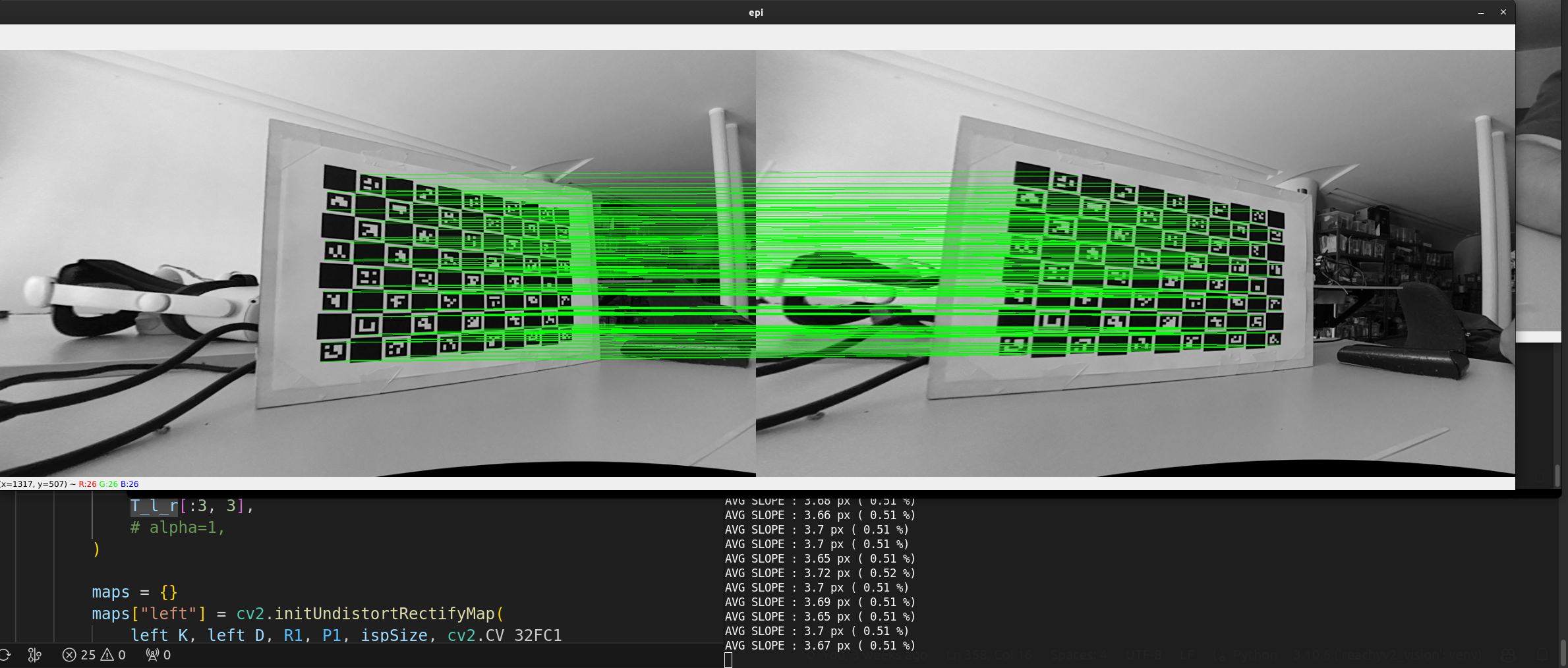
      Using ImageManip with setWarpMesh() with the returned mesh works ok, I have an average epipolar error of about 0.5% (~3.5px on a 720p image, see image below)
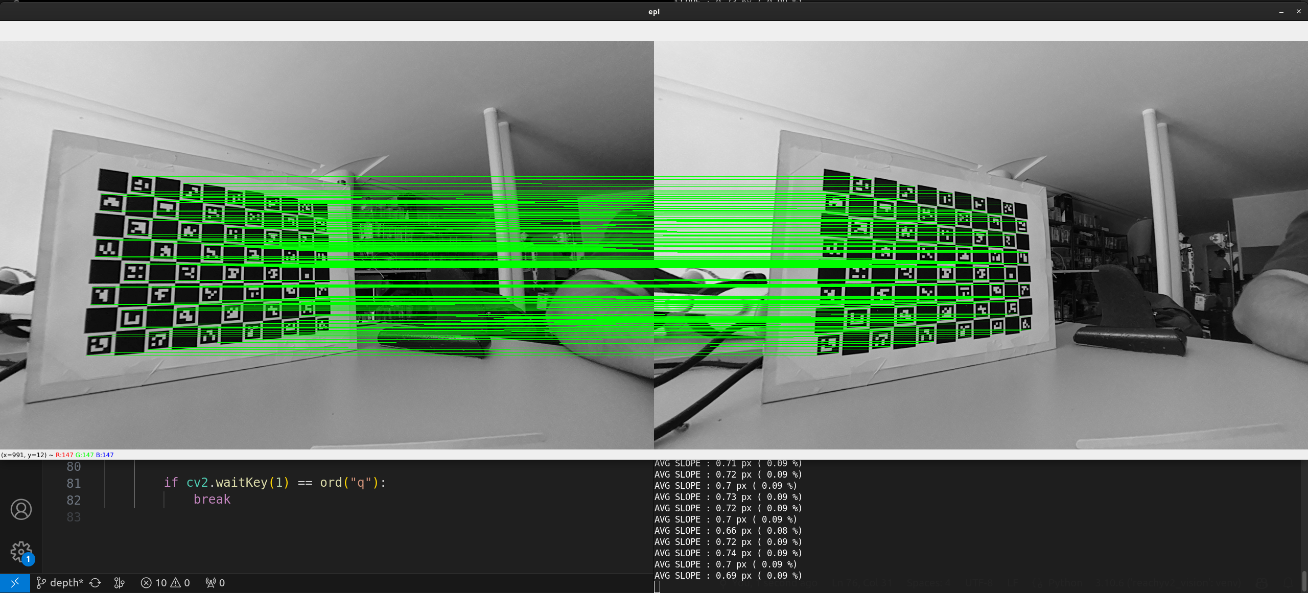
      Using the same calibration results (intrinsics and extrinsics) and the StereoDepth node, computing the epipolar error on the rectified left and right images that the node outputs, I get much better results (about 0.09%, 0.69px on a 720p image, see image below)
      Here is how I compute the epilines score for reference

      
      def drawEpiLines(left, right, aruco_dict):
          concatIm = np.hstack((left, right))
      
          lcorners, lids, _ = aruco.detectMarkers(image=left, dictionary=aruco_dict)
          rcorners, rids, _ = aruco.detectMarkers(image=right, dictionary=aruco_dict)
      
          if len(lcorners) == 0 or len(rcorners) == 0:
              return concatIm
      
          lids = lids.reshape(-1)
          rids = rids.reshape(-1)
      
          lcorners_dict = {}
          for i in range(len(lids)):
              lid = lids[i]
              lcorners_dict[lid] = lcorners[i].reshape((-1, 2))
      
          rcorners_dict = {}
          for i in range(len(rids)):
              rid = rids[i]
              rcorners_dict[rid] = rcorners[i].reshape((-1, 2))
      
          avg_slope = []
      
          for lid in lids:
              if lid not in rids:
                  continue
      
              lcorners = lcorners_dict[lid]
              rcorners = rcorners_dict[lid]
              for i in range(len(lcorners)):
                  x1 = lcorners[i][0]
                  y1 = lcorners[i][1]
                  x2 = rcorners[i][0] + left.shape[1]
                  y2 = rcorners[i][1]
                  avg_slope.append(abs(y2 - y1))
                  cv2.line(
                      concatIm,
                      (int(x1), int(y1)),
                      (int(x2), int(y2)),
                      (0, 255, 0),
                      1,
                  )
      
          avg_slope = np.mean(avg_slope)
          avg_slope_percent = avg_slope / left.shape[0] * 100
          print(
              "AVG SLOPE :",
              round(avg_slope, 2),
              "px (",
              round(abs(avg_slope_percent), 2),
              "%)",
          )
          return concatIm

      I have two questions:

      • Do you have an idea of what could explain this difference ?
      • Do you have any plans to add the support of rectified color images as output of the StereoDepth node ? (We use IMX296 color cameras right now)

      Thanks !

        4 days later

        Hi apirrone
        Sorry for the late reply, was unsure how to reply. The only cause of the difference I could think of is due to optimizations done on our hardware accelerated functions.

        Regarding the rectified color streams, I'd say no. Right now the rectified streams are grayscale and right now, there is no real need for a color output. Will ask the team just to make sure.

        EDIT:
        There is a plan to add the color rectified output in the future. It's low priority so not sure when it will be implemented.

        Thanks,
        Jaka

          5 days later

          Hi Jaka, I have three AR0234 colour cameras connected to my 3P and when I try to align RGB to a depth image from camera sockets B or C (left of right as standard) the image doesn't seem to match properly. Is this related to the behaviour of colour cameras not being rectified in the same way?

          In my use case I have wide angle lenses on the stereo pair and a narrower lens in the centre. The idea was to use the matching colour frame from one of the wide angle lenses to colourise the depth image or point cloud. This means I have the benefit of colour point clouds matching the wider angles but also have the narrower view from the centre camera for object recognition purposes at greater distances.

          HFOV of the lenses are currently 110, 90, 110. I'm trying to find a slightly narrower one for centre at the minute without any luck.

          I was confused as I can't remember Jaka saying it's on the roadmap before, must've edited while I was typing! 🤣

          Good to know it's on the roadmap, hopefully the pointcloud node will appear alongside it. 🙂

          7 months later

          jakaskerl

          Sorry to necro but do we know when this might be added? Not being able to get rectified/aligned color from the sr when all our other cameras in a multi-camera scene can makes for creating color occupancy maps with your cameras a non-starter if we want to use the sr.

          Hi @ViWalkerDev
          Difficult to achieve due to HW constraints of the RVC2. It is running slower than acceptable, so we won't be doing it on RVC2, only on RVC4.

          Thanks,
          Jaka

          3 months later

          @apirrone I found a bug in rgb_undistort (see PR). I also changed meshCellSize from 16 to 20. And now, your code works perfectly for me, and I get a rectified color image from ImageManip that is the same as the grayscale coming from StereoDepth. I didn't check the epipolar error like you did, but the diff in images is minimal now, maybe just because of interpolation.

          Sorry, a correction: what is working for me is to generate the mesh based on the rectification homography, like in luxonis/depthai-experimentstree/master/gen2-stereo-on-host. So that's:

              cv::Mat M_left = toCvMat(calibHandler.getCameraIntrinsics(CameraBoardSocket::CAM_B, 1280, 800));
              cv::Mat M_right =
                  toCvMat(calibHandler.getCameraIntrinsics(CameraBoardSocket::CAM_C, 1280, 800));
              cv::Mat R1 = toCvMat(calibHandler.getStereoLeftRectificationRotation());
          
              rectH_left = M_right * R1 * M_left.inv();
          
              // Generate maps from the rectification homography
              auto eye = cv::Matx<float, 3, 3>::eye();
              cv::initUndistortRectifyMap(
                  eye, cv::Mat(), rectH_left, eye, cv::Size(1280, 800), CV_32FC1, rectMapX, rectMapY
              );
          
              // Generate mesh based on these maps, instead of the cv::stereoRectify maps
              // [...]

          (I'm using the AR0234; adjust 1280 and 800 (ispWidth and ispHeight) accordingly.